
Datasheet


MCP454X/456X/464X/466X
DS22107B-page 60 2008-2013 Microchip Technology Inc.
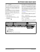
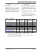
7.5 Read Data
Normal and High Voltage
The Read Command can be issued to both the Volatile
and Nonvolatile memory locations. The format of the
command, see Figure 7-4, includes the Start condition,
I
2
C Control Byte (with R/W bit set to “0”), A bit,
MCP4XXX Command Byte, A bit, followed by a
Repeated Start bit, I
2
C Control Byte (with R/W bit set to
“1”), and the MCP4XXX transmitting the requested
Data High Byte, and A bit, the Data Low Byte, the Mas-
ter generating the A
, and Stop condition.
The I
2
C Control Byte requires the R/W bit equal to a
logic one (R/W = 1) to generate a read sequence. The
memory location read will be the last address
contained in a valid write MCP4XXX Command Byte or
address 00h if no write operations have occurred since
the device was reset (Power-on Reset or Brown-out
Reset).
During a write cycle (Write or High Voltage Write to a
Nonvolatile memory location) the Read command can
only read the Volatile memory locations. By reading the
Status Register (04h), the Host Controller can
determine when the write cycle has completed (via the
state of the EEWA bit).
Read operations initially include the same address byte
sequence as the write sequence (shown in Figure 6-9).
This sequence is followed by another control byte
(including the Start condition and Ackowledge) with the
R/W bit equal to a logic one (R/W = 1) to indicate a
read. The MCP4XXX will then transmit the data con-
tained in the addressed register. This is followed by the
master generating an A bit in preparation for more data,
or an A
bit followed by a Stop. The sequence is ended
with the master generating a Stop or Restart condition.
The internal address pointer is maintained. If this
address pointer is for a nonvolatile memory address
and the read control byte addresses the device during
a Nonvolatile Write Cycle (t
WC
) the device will respond
with an A
bit.
7.5.1 SINGLE READ
Figure 7-4 show the waveforms for a single read.
For single reads the master sends a STOP or
RESTART condition after the data byte is sent from the
slave.
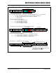
7.5.1.1 Random Read
Figure 7-5 shows the sequence for a Random Reads.
Refer to Figure 7-5 for the random byte read
sequence.
7.5.2 CONTINUOUS READS
Continuous reads allows the device’s memory to be
read quickly. Continuous reads are possible to all mem-
ory locations. If a nonvolatile memory write cycle is
occurring, then Read commands may only access the
volatile memory locations.
Figure 7-6 shows the sequence for three continuous
reads.
For continuous reads, instead of transmitting a Stop
or Restart condition after the data transfer, the master
reads the next data byte. The sequence ends with the
master Not Acknowledging and then sending a Stop or
Restart.
7.5.3 THE HIGH VOLTAGE COMMAND
(HVC) SIGNAL
The High Voltage Command (HVC) signal is
multiplexed with Address 0 (A0) and is used to indicate
that the command, or sequence of commands, are in
the High Voltage mode. High Voltage commands allow
the device’s WiperLock Technology and write protect
features to be enabled and disabled.
The HVC pin has an internal resistor connection to the
MCP4XXXs internal V
DD
signal.
7.5.4 IGNORING AN I
2
C TRANSMISSION AND
“FALLING OFF” THE BUS
The MCP4XXX expects to receive entire, valid I
2
C
commands and will assume any command not defined
as a valid command is due to a bus corruption and will
enter a passive high condition on the SDA signal. All
signals will be ignored until the next valid Start
condition and Control Byte are received.