
User manual

MCP42XXEV Evaluation Board User’s Guide
DS51898A-page 16 2010 Microchip Technology Inc.
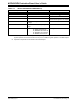
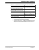
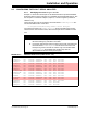
TABLE 2-1: INSTALLED PASSIVE COMPONENTS
(2)
Component Description Comment
R11U, R17U 0 SMT 805 Pull-up resistor
R14U, R15U 10 k SMT 805 Pull-up resistor
R7D, R13D 0 SMT 805 Pull-down resistor
(1)
U3 MCP4261-103E/ST R
AB(TYP)
= 10 k
Device bottom aligned in U3 footprint
P9, P12 Test Point – through-hole connector
(orange)
J1 1x6 Male Header, 100 mil spacing 90°
angle.
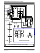
PICkit™ Serial/ICSP™ Header
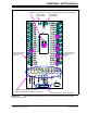
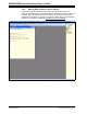
— Blue Wire:
J1 CS/NC via to P4 via
J1 SDI/SDA via to P16 via
J1 SCK/SCL via to P5 via
J1 SDO/NC via to P6 via
See Figure 2-2
Note 1: Whichever pin is the device’s V
DD
pin, that corresponding RXD footprint can be used for the device’s
bypass capacitor. So if Pin 8 is the device’s V
DD
pin, then install the bypass capacitor in the R8D footprint.
2: All passive components use the surface mount 805 footprint.