
User manual

MCP42XXEV Evaluation Board User’s Guide
DS51898A-page 12 2010 Microchip Technology Inc.
2.2 FEATURES
The MCP42XXEV Evaluation Board has the following features:
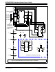
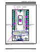
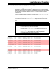
• MCP4261-103E/ST is installed (bottom aligned in U3)
•0 resistors connect MCP4261 V
DD
and V
SS
signals to the appropriate power or
ground plane (see Figure 2-2)
•0 resistors connect MCP4261’s Resistor Network 0 A terminal signal to power
plane, resistor network is in a voltage divider configuration (see Figure 2-2)
•0 resistors connect MCP4261’s Resistor Network 0 B terminal signal to ground
plane, resistor network is in a voltage divider configuration (see Figure 2-2)
• Through-hole connection terminal (orange) for all wiper pins
• Connection terminal points for all device pins (either through-hole or
surface-mount)
• Footprints for optional passive components (SMT 805 footprint) for:
- Power supply filtering (C
1
and C
2
footprints)
- Device bypass capacitor (RxD footprint for device pin connected to V
DD
)
• Silk-screen area to write specifics of implemented circuit (on back of PCB), such
as MCP4261 10 k
• PICkit Serial Analyzer Header
The included TSSOP20EV board has the following features:
• Connection terminals may be either through-hole or surface-mount
• Three package type footprints supported:
-TSSOP-20
-TSSOP-14
-TSSOP-8
-SSOP-20
- DIP-20 (600 mil body)
• Footprints for optional passive components (SMT 805 footprint) for:
- Power supply filtering (C
1
and C
2
footprints)
- Device bypass capacitor (RxD footprint for device pin connected to V
DD
)
- Output filtering (RxD footprint)
- Output pull-up resistor (RxU footprint)
- Output pull-down resistor (RxD footprint)
- Output loading resistor (RxD footprint)
• Silk-screen area to write specifics of implemented circuit (on back of PCB), such
as MCP4261 10 k
• PICkit Serial Analyzer/PICkit 2 programming (ICSP™) Header