MCP42XXEV Evaluation Board User’s Guide 2010 Microchip Technology Inc.
Note the following details of the code protection feature on Microchip devices: • Microchip products meet the specification contained in their particular Microchip Data Sheet. • Microchip believes that its family of products is one of the most secure families of its kind on the market today, when used in the intended manner and under normal conditions. • There are dishonest and possibly illegal methods used to breach the code protection feature.
MCP42XXEV EVALUATION BOARD USER’S GUIDE Table of Contents Preface ........................................................................................................................... 5 Chapter 1. Product Overview 1.1 Introduction ..................................................................................................... 9 1.2 What is the MCP42XXEV Evaluation Board? ................................................ 9 1.3 What the MCP42XXEV Evaluation Board Kit Includes .......................
MCP42XXEV Evaluation Board User’s Guide NOTES: DS51898A-page 4 2010 Microchip Technology Inc.
MCP42XXEV EVALUATION BOARD USER’S GUIDE Preface NOTICE TO CUSTOMERS All documentation becomes dated, and this manual is no exception. Microchip tools and documentation are constantly evolving to meet customer needs, so some actual dialogs and/or tool descriptions may differ from those in this document. Please refer to our web site (www.microchip.com) to obtain the latest documentation available. Documents are identified with a “DS” number.
MCP42XXEV Evaluation Board User’s Guide CONVENTIONS USED IN THIS GUIDE This manual uses the following documentation conventions: DOCUMENTATION CONVENTIONS Description Arial font: Italic characters Initial caps Quotes Underlined, italic text with right angle bracket Bold characters N‘Rnnnn Text in angle brackets < > DS51898A-page 6 Represents Examples Referenced books Emphasized text A window A dialog A menu selection A field name in a window or dialog A menu path MPLAB® IDE User’s Guide ...
Preface RECOMMENDED READING This user’s guide describes how to use the MCP42XXEV Evaluation Board. Other useful documents are listed below. The following Microchip documents are available and recommended as supplemental reference resources.
MCP42XXEV Evaluation Board User’s Guide DOCUMENT REVISION HISTORY Revision A (April 2010) • Initial Release of this Document. DS51898A-page 8 2010 Microchip Technology Inc.
MCP42XXEV EVALUATION BOARD USER’S GUIDE Chapter 1. Product Overview 1.1 INTRODUCTION This chapter provides an overview of the MCP42XXEV Evaluation Board and covers the following topics: • What is the MCP42XXEV Evaluation Board? • What the MCP42XXEV Evaluation Board kit includes 1.2 WHAT IS THE MCP42XXEV EVALUATION BOARD? The MCP42XXEV Evaluation Board allows the system designer to quickly evaluate the operation of Microchip Technology’s MCP4261 Digital Potentiometer device.
MCP42XXEV Evaluation Board User’s Guide Connected to Ground Plane Connected to Power Plane 0 4261 MCP4261-103E/ST installed in U3 (TSSOP-14 package bottom aligned to TSSOP-20 footprint) 10 k 10 k 0 Through hole Test Point (Orange) Wiper 1 Four Blue Wire Jumpers to connect PICkit™ Serial interface (SPI) to device pins 0 Through hole Test Point (Orange) Wiper 0 0 1x6 Male Header, with 90 right angle FIGURE 1-1: MCP42XXEV Evaluation Board Using the TSSOP20EV Evaluation Board (MCP4361 instal
MCP42XXEV EVALUATION BOARD USER’S GUIDE Chapter 2. Installation and Operation 2.1 INTRODUCTION The MCP42XXEV Evaluation Board allows the system designer to quickly evaluate the operation of the MCP4261 10 k (-103) digital potentiometer device using the PICkit Serial Analyzer. The PICkit Serial Analyzer is available separately (order number: DV164122). This board is a minimum configuration for the device.
MCP42XXEV Evaluation Board User’s Guide 2.
Installation and Operation 2.3 GETTING STARTED The MCP42XXEV Evaluation Board allows quick evaluation of the MCP4261-103E/ST device. The understanding of the device characteristics (such as the resistor network) is applicable to any of the devices in the MCP42XX family. The MCP4261-103 device has a typically RAB resistance of 10 k.
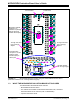
MCP42XXEV Evaluation Board User’s Guide P1 P2 DIP-20 (1) P9 PICkit™ Serial/ICSP™ Interface J1 NC VDD VSS SDA SCL NC NC VDD VSS SDI SCK SDO 1 P20 20 P19 19 2 P12 9 12 P11 10 11 Requires blue wire jumpering to connect the PICkit™ Interface to the selected device P10 R1U TSSOP-20 (1) VDD 20 2 19 9 12 10 11 VSS P1 R1D 1 C2 C1 R2U P2 R2D P19 P11 R19U P19 R19D P20 SSOP-20 P1 1 20 2 19 XTAL P9 P12 P2 P10 9 12 VIA1 10 11 C3 VIA2 C4 R20U P20 PIC® MCU Circuitry (bottom o
Installation and Operation MCP4261-103E/ST Installed in U3 (TSSOP-14 package bottom aligned to TSSOP-20 footprint) Connected to Connected to Ground Plane Power Plane 4261 0 10 k 10 k 0 Through hole Test Point (Orange) Wiper 1 0 Through hole Test Point (Orange) Wiper 0 0 Four Blue Wire Jumpers to connect PICkit™ Serial interface (SPI) to device pins 1x6 Male Header, with 90 right angle FIGURE 2-2: MCP42XXEV Evaluation Board Component Placement Using the TSSOP20EV Evaluation Board (Top).
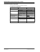
MCP42XXEV Evaluation Board User’s Guide TABLE 2-1: INSTALLED PASSIVE COMPONENTS (2) Component Description Comment R11U, R17U 0 SMT 805 Pull-up resistor R14U, R15U 10 k SMT 805 Pull-up resistor R7D, R13D 0 SMT 805 Pull-down resistor (1) U3 MCP4261-103E/ST RAB(TYP) = 10 k Device bottom aligned in U3 footprint P9, P12 Test Point – through-hole connector (orange) J1 1x6 Male Header, 100 mil spacing 90° angle.
Installation and Operation TABLE 2-2: OPTIONAL PASSIVE COMPONENTS – NOT INSTALLED (2) Component Comment C1, C2 Power supply bypass capacitors (3) C3, C4 PIC® MCU Crystal capacitors R1U, R2U, R3U, R4U, R5U, R6U, R7U, R8U, R9U, R12U, R13U, R16U, R18U, R19U, R20U Pull-up resistor R1D, R2D, R3D, R4D, R5D, R6D, R8D, R9D, R10D, R11D, R12D, R14D, R15D, R16D, R17D, R18D, R19D, R20D Pull-down resistor (1) U1, U2 Alternate package footprints VDD, GND Power and Ground plane connection points Y1 Can con
MCP42XXEV Evaluation Board User’s Guide 2.4.2 The MCP4261 Device To make variations to the commands sent to the MCP4261 device (from the commands shown in the demo section), one must know the device memory map (see Table 2-3) and the command formats (see Figure 2-3). For additional device operational information, refer to the MCP4261 device data sheet (DS22059).
Installation and Operation 2.5 CONFIGURING THE PICkit™ SERIAL ANALYZER 2.5.1 Modifying the CommScripts.txt file Example 2-1 shows the User Scripts for the MCP43XX devices (from MCP43XXEV Evaluation Board). These script files are compatible with the MCP42XX devices, with the exception of commands to Wiper 2, Wiper 3, or TCON1 registers (commands shaded in red). These User Scripts need to be added to the PICkit serial’s CommScripts.txt file.
MCP42XXEV Evaluation Board User’s Guide 2.5.2 Working With the PICkit™ Serial Analyzer Figure 2-4 shows the PICkit Serial window after the program has started. The Transaction window indicates if the PICkit serial GUI located the PICkit Serial Analyzer hardware. When starting the PICkit Serial Analyzer for the first time, some setup questions may be asked. If you have any questions, please refer to the PICkit Serial Analyzer documentation, available at www.Microchip.com/PICkitSerial.
Installation and Operation We need to select the PICkit Serial Analyzer GUI to be in SPI Master mode. Figure 2-5 shows how to select the proper mode. Select PICkit Serial Analyzer -> Select Communications Mode -> SPI Master menu item (make sure the SPI Master item is checked). FIGURE 2-5: PICkit™ Serial Selecting Communications Mode. 2010 Microchip Technology Inc.
MCP42XXEV Evaluation Board User’s Guide Now we need to configure the mode that we selected. Figure 2-6 shows how to configure the Communications mode. Select PICkit Serial Analyzer -> Configure Communications Mode menu item. This will open a new window: FIGURE 2-6: DS51898A-page 22 PICkit™ Serial Main Window at Start-up. 2010 Microchip Technology Inc.
Installation and Operation Figure 2-7 shows the Configure Communications Mode window. Ensure that your window options and settings are the same as this window, and then select the Save Changes button. The Configure Communications Mode window may now be closed. FIGURE 2-7: PICkit™ Serial Configure Communications Mode Window. 2010 Microchip Technology Inc.
MCP42XXEV Evaluation Board User’s Guide Now we are going to open the Script Builder window, select the Communications -> Script -> Script Builder menu item (see Figure 2-8). FIGURE 2-8: DS51898A-page 24 PICkit™ Serial – Script Builder Menu Selection. 2010 Microchip Technology Inc.
Installation and Operation The Script Builder window is shown in Figure 2-9. In this window we see the User SPI Scripts including the ones that were added to the CommScripts.txt file. FIGURE 2-9: PICkit™ Serial Main Window at Start-up. 2010 Microchip Technology Inc.
MCP42XXEV Evaluation Board User’s Guide Double clicking on the WriteWiper0 User SPI Script will load the script details. Figure 2-10 shows what the values mean in the Script Details. These values are hex numbers. The first value (02h), is the number of bytes that will be written. The second byte is a data byte and contains the device register address, the Device command, and the two Most Significant bits (MSb) of the write data.
Installation and Operation Double clicking on the ReadWiper0 User SPI Script will load the script details. Figure 2-11 shows what the values mean in the Script Details. These values are hex numbers. The first value (02h), is the number of bytes that will be written. The second byte is a data byte and contains the device register address, the Device command, and the two Most Significant bits (MSb) of the read data. The third byte is the 2nd data byte and contains the remaining 8 bits of the read data.
MCP42XXEV Evaluation Board User’s Guide 2.6 MCP4261 DEMO STEPS This demo assumes that you know how to configure the PICkit Serial Analyzer for Master SPI operation. See Section 2.5 “Configuring The PICkit™ Serial Analyzer” or the “PICkit Serial Analyzer User’s Guide” (DS51647) for additional information. 1. 2. 3. 4. 5. 6. 7. 8. 9. 10. 11. 12. 13. 14. 15. 16. 17. 18. 19. 20. DS51898A-page 28 Plug the PICkit serial device into the PC’s USB port. Plug the MCP42XXEV board into the PICkit serial.
Installation and Operation 21. Select the “DECRWiper0” script in the User SPI Scripts column and then click on the Execute Script button three times. 22. Select the “ReadWiper0” script in the User SPI Scripts column and then click on the Execute Script button. The Transaction window shows the scripts that were executed and the current value of the Wiper 0 (see Figure 2-14). 23. In the Transaction window, click the Clear button. 24. On the PICkit Serial Analyzer command bar, click the Reset button. 25.
MCP42XXEV Evaluation Board User’s Guide 9-bit data value (03Fh) written to Wiper 0 register 9-bit data value (1FFh) written to Wiper 0 register FIGURE 2-13: 9-bit data value (03Fh) read from Wiper 0 register 9-bit data value (1FFh) read from Wiper 0 register MCP4261 Transaction Window – Wiper 0 Writes and Reads.
Installation and Operation Data value (03Fh) read from Wiper 0 register Data value (042h) read from Wiper 0 register after 3 Increment Commands FIGURE 2-15: MCP4261 Transaction Window – Wiper 0 Increments. 2010 Microchip Technology Inc.
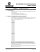
MCP42XXEV Evaluation Board User’s Guide 2.6.1 The TSSOP20EV PCB and Supported Digital Potentiometers Table 2-4 shows the current digital potentiometers that are supported by the TSSOP20EV PCB.
MCP42XXEV EVALUATION BOARD USER’S GUIDE Appendix A. Schematic and Layouts A.1 INTRODUCTION This appendix contains the schematics and layouts for the MCP42XXEV Evaluation Board. Diagrams included in this appendix: • • • • • • • A.
MCP42XXEV Evaluation Board User’s Guide BOARD – SCHEMATIC M A.3 DS51898A-page 34 2010 Microchip Technology Inc.
Schematic and Layouts A.4 BOARD – TOP TRACE, SILK AND PADS 2010 Microchip Technology Inc.
MCP42XXEV Evaluation Board User’s Guide A.5 BOARD – BOTTOM TRACE AND PADS DS51898A-page 36 2010 Microchip Technology Inc.
Schematic and Layouts A.6 BOARD – LAYER 2 GROUND PLANE 2010 Microchip Technology Inc.
MCP42XXEV Evaluation Board User’s Guide A.7 BOARD – LAYER 3 POWER PLANE DS51898A-page 38 2010 Microchip Technology Inc.
Schematic and Layouts A.8 BOARD LAYOUT – TOP COMPONENTS 2010 Microchip Technology Inc.
MCP42XXEV Evaluation Board User’s Guide A.9 BOARD – BOTTOM SILK, TRACE AND PADS DS51898A-page 40 2010 Microchip Technology Inc.
MCP42XXEV EVALUATION BOARD USER’S GUIDE Appendix B. Bill of Materials (BOM) TABLE B-1: Qty BILL OF MATERIALS Reference Description 1 J1 CONN HEADER 6POS .100 R/A TIN 2 P9, P12 1 PCB TEST POINT PC MULTI PURPOSE THROUGH HOLE (Orange) Note 1 2 4 R14U, R15U R7D, R11U R13D, R17U U3 1 Note 1: 2: RES 10K OHM 1/8W 5% 0805 SMD RES 0.0 OHM 1/8W 5% 0805 SMD Manufacturer Part Number Molex/Waldom Electronics Corp Keystone Electronics 22-05-2061 Microchip Technology Inc.
WORLDWIDE SALES AND SERVICE AMERICAS ASIA/PACIFIC ASIA/PACIFIC EUROPE Corporate Office 2355 West Chandler Blvd. Chandler, AZ 85224-6199 Tel: 480-792-7200 Fax: 480-792-7277 Technical Support: http://support.microchip.com Web Address: www.microchip.