
User manual
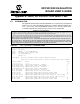
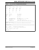
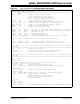
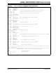
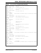
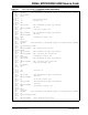
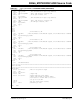
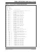

00066_MCP402XEV.ASM Source Code
© 2005 Microchip Technology Inc. DS51546B-page 31
;**********************************************************************************************
; General Pupose Register Definitions
;**********************************************************************************************
GPRS UDATA
State res 1 ; variable to track the “state” value
; this code functions as a state machine
; bits 3:0 stores the state 0-15 indicator
; bits 7:6 stores the debounced button states
OldState res 1 ; allows program to see if State changed
Exit res 1 ; variable to count the number ms to test for a button press
DebounceUP res 1 ; variable to count the number of ms UP was pressed
DebounceDOWN res 1 ; variable to count the number of ms DOWN was pressed
DLYCNT1 res 1 ; variable for the delay subroutines
DLYCNT2 res 1 ; variable for the delay subroutines
#define UD GPIO,1 ; GP1 tied to UD & has “INCR” switch connected via 2.2k resistor
#define CS GPIO,0 ; GP0 tied to CS & has “DECR” switch connected via 2.2k resistor
#define UP GPIO,1 ; Momentary switch UP
#define DOWN GPIO,0 ; Momentary switch DOWN
#define CP GPIO,2 ; OSCOUT pin for Charge Pump
#define PowerDown GPIO,3 ; Vpp for programming & PowerDown input to put uC to SLEEP
#define HV_CS OSCCAL,FOSC4 ; Drives CS to HVDD (drive CS high first)
#define UP_State State,7 ; Debounced UP State - using bits 5:4 are critical
#define DOWN_State State,6 ; Debounced DOWN State - using bits 5:4 are critical
;***********************************************************************************************
; Reset Code
;***********************************************************************************************
RESET CODE ; processor reset vector + 1
;ResetVector ; Device resets to 0x1FF to get the factory calibration
goto Start ; Lower half of memory reserved for subroutines
;***********************************************************************************************
; Main Code
;***********************************************************************************************
MAIN CODE
Start
Init_Oscillator
; Internal RC calibration value is placed at location 0xFF by Microchip
; as a movlw k, where the k is a literal value.
movwf OSCCAL ; update register with factory cal value
; bcf OSCCAL,FOSC4 ; make sure the FOSC4 is disabled to shut charge pump off
StateMachineReset
movlw b’11110011’ ; Disable the Comparator & make inputs digital
movwf CMCON0
; bcf CMCON0, CMPON ; needs to be on to get GP2 as a General Purpose Output
movlw b’10011010’ ; disable Wake-Up on Pin Change,
; enable weak pullups for button inputs
; T0CS must be 0 for GP2 TRIS to be active
; set up for 72ms WDT
option
Init
clrf State
clrf OldState
call InitGPIO ; make GP0/DECR/CS & GP1/INCR/UD outputs, block undesired U/D commands
TABLE E-1: 00066_MCP402XEV.ASM SOURCE CODE (CONTINUED)