
User manual


MCP401X/2X EVALUATION
BOARD USER’S GUIDE
© 2005 Microchip Technology Inc. DS51546B-page 25
Appendix C. Using the BFMP Programmer to Power the Board
C.1 POWERING THE BOARD USING THE BFMP PROGRAMMER
The BFMP programmer (PG164101) uses a 6-pin interface for programming. The
PICkit™ 2 Flash Starter Kit (PG164120 or DV164120) uses the same interface.
The MCP402X Digital Potentiometer Evaluation Board (MCP402XEV) plugs into the
BFMP (or PICkit™ 2 Flash Starter Kit) in the orientation shown in Figure C-1.
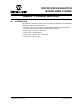
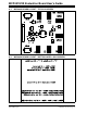
FIGURE C-1: BFMP Hardware and MCP402X Digital Potentiometer Evaluation
Board.
USB Cable to PC
BFMP Board
(Top-side)
BFMP Header connector
MCP402XEV
Board
(Bottom-side)
Pin #1 Pin #1