
User manual


MCP401X/2X EVALUATION
BOARD USER’S GUIDE
© 2005 Microchip Technology Inc. DS51546B-page 19
Appendix A. Schematic and Layouts
A.1 INTRODUCTION
This appendix contains the following schematics and layout diagrams for the MCP402X
Digital Potentiometer Evaluation Board.
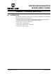
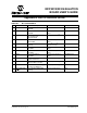
• Schematic – Shows the schematic of the MCP402X Digital Potentiometer Evalua-
tion Board. The populated PCB was built using this schematic.
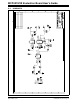
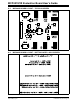
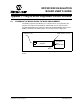
• Board Layout – Top Layer + Silk-screen
• Board Layout – Top Silk-Screen
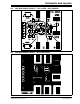
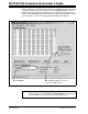
• Board Layout – Bottom Layer + Silk-screen
• Board Layout – Bottom Layer