
User manual

MCP401X/2X Evaluation Board User’s Guide
DS51546B-page 16 © 2005 Microchip Technology Inc.
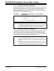
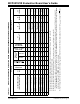
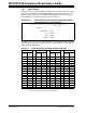
2.3.4 Wiper Voltages
Table 2-3 shows the relation between the wiper position and the voltage on the wiper
when 5.0 volts is applied to the MCP402X Digital Potentiometer Evaluation Board
where the resistors R2 and R3 are 2500Ω and the MCP4011 resistor value (R
AB
) is
10 kΩ. Equation 2-4 shows the formula for these calculations.
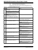
EQUATION 2-4: CALCULATING THE VOLTAGE ON THE MCP402X DIGITAL
POTENTIOMETER EVALUATION BOARD
The typical step resistance for the 10 kΩ MCP4021 is approximately 158.73Ω. With a
5V supply and a 15 kΩ total resistance (2.5 kΩ + 2.5 kΩ + 10 kΩ), the delta voltage per
step is approximately 0.053V.
TABLE 2-3: WIPER POSITION AND CORRESPONDING VOLTAGE
Wiper Wiper Wiper Wiper
Position
Voltage
(V)
Position
Voltage
(V)
Position
Voltage
(V)
Position
Voltage
(V)
00
(1)
0.833 16 1.680 32 2.526 48 3.373
01 0.866 17 1.733 33 2.579 49 3.426
02 0.939 18 1.786 34 2.632 50 3.479
03 0.992 19 1.839 35 2.685 51 3.532
04 1.045 20 1.892 36 2.738 52 3.585
05 1.098 21 1.944 37 2.791 53 3.638
06 1.151 22 1.997 38 2.844 54 3.690
07 1.204 23 2.050 39 2.897 55 3.743
08 1.257 24 2.103 40 2.950 56 3.796
09 1.310 25 2.156 41 3.003 57 3.849
10 1.362 26 2.209 42 3.056 58 3.902
11 1.415 27 2.262 43 3.108 59 3.955
12 1.468 28 2.315 44 3.161 60 4.008
13 1.521 29 2.368 45 3.214 61 4.061
14 1.574 30 2.421 46 3.267 62 4.114
15 1.627 31 2.474 47 3.320 63
(2)
4.167
Note 1: This is zero-scale, wiper is connected to terminal B.
2: This is full-scale, wiper is connected to terminal A.
Voltage at Wiper System V
DD
R3 Wiper Position R
AB
()63ڥ()+()
R3 R
AB
R2++
-----------------------------------------------------------------------------------------
•=
Where:
System V
DD
=
5.0V
R2
=
2.5 kΩ
R3
=
2.5 kΩ
R
AB
=
10 kΩ