
User manual

MCP401X/2X Evaluation Board User’s Guide
DS51546B-page 14 © 2005 Microchip Technology Inc.
2.3.3 Running the Ratiometric Voltage Demo
Table 2-2 provides step-by-step instructions to perform a demonstration of the
MCP402X Digital Potentiometer Evaluation Board. Measuring Ratiometric Voltage
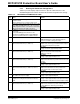
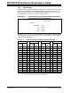
TABLE 2-2: MEASURING RATIOMETRIC VOLTAGE
Step Action Result
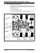
1 Power up the populated Digital Potentiometer
Evaluation Board.
Voltage calculations use a system voltage of 5V.
—
Board can be powered via a valid voltage (such as 5V)
on the VDD and GND PCB Pads, or by connecting a
BFMP programmer that is connected to an active PC’s
USB port (powered via the USB connection).
2 Set DMM to measure the required voltage range
(0V to 5.5V).
Connect the DMM ground connection to the
evaluation board GND terminal and the DMM V/Ω
connection to terminal W of the evaluation board.
—
3 Turn on DMM. On DMM:
DMM will display the voltage determined by the
current non-volatile setting of the wiper.
4 On the Digital Potentiometer Evaluation Board:
Implement Command #5 (see Table 2-1).
On the Digital Potentiometer Evaluation Board:
WiperLock™ Technology is disabled and the wiper is
incremented from power-on position.
On DMM:
Voltage increments approximately 0.05V.
5 On the Digital Potentiometer Evaluation Board:
Implement Command #4 (see Table 2-1).
On the Digital Potentiometer Evaluation Board:
Wiper is forced to the full-scale position
(Wiper W = node A).
On DMM:
Voltage equals approximately 4.17V.
6 On the Digital Potentiometer Evaluation Board:
Implement Command #6 (see Table 2-1).
On the Digital Potentiometer Evaluation Board:
Wiper is decremented one position from the full-scale
position.
On DMM:
Voltage equals approximately 4.12V.
7 On the Digital Potentiometer Evaluation Board:
Implement Command #6 (see Table 2-1) 15 more
times.
On the Digital Potentiometer Evaluation Board:
Wiper is decremented to the 25% position from
node A (full-scale) to node B (zero-scale).
On DMM:
Voltage equals approximately 3.33V.
8 On the Digital Potentiometer Evaluation Board:
Turn off/disconnect power supply.
On DMM:
Voltage equals approximately 0V.
9 On the Digital Potentiometer Evaluation Board:
Reapply power to Digital Potentiometer Evaluation
Board.
On DMM:
Voltage equals approximately 3.33V. This shows that
the MCP4021 retained the last selected wiper setting.
10 On the Digital Potentiometer Evaluation Board:
Implement Command #3 (see Table 2-1).
On the Digital Potentiometer Evaluation Board:
Wiper is incremented one position and the wiper is
locked (WiperLock Technology is enabled).
On DMM:
Voltage equals approximately 3.38V.