
User manual

Installation and Operation
© 2005 Microchip Technology Inc. DS51546B-page 11
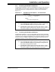
2.3.1 Test Setup
1. Connect the power supply “+” to VDD and the “–” to GND.
2. Connect the voltmeter to the W terminal and GND.
The voltmeter should reflect the wiper setting with respect to Equation 2-3.
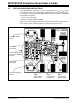
EQUATION 2-3: POPULATED PCB – VOLTAGE DIVIDER CALCULATION
Using R2 and R3 = 2.5 kΩ:
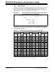
• If a 2 kΩ MCP4021 is utilized, the output range will be approximately 1.79V to
3.21V.
• If a 5 kΩ MCP4021 is utilized, the output range will be approximately 1.25V to
3.75V.
• If a 10 kΩ MCP4021 is utilized, the output range will be approximately 0.83V to
4.17V.
• If a 50 kΩ MCP4021 is utilized, the output range will be approximately 0.23V to
4.77V.
V
wiper
V
DD
R
wb
R3+()⋅
R2 R3 R
AB
++
-------------------------------------------
5.0V d 10k
⋅
()63
⁄
2.5k+()
⋅
2.5k 2.5k 10k++
---------------------------------------------------------------------
==
Where:
d = the wiper setting (0 to 63)