
User manual

Installation and Operation
© 2005 Microchip Technology Inc. DS51546B-page 9
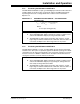
2.2.3 Evaluating the MCP4023 and MCP4013
The MCP4023/13-XXXI/OT is a 6-pin, grounded digital potentiometer with terminals A
and W available on the device pins. Footprint U2 supports the SOT-23-6 package.
Populating R2 will create a voltage divider with a transfer function illustrated in
Equation 2-2.
EQUATION 2-2: GROUNDED POTENTIOMETER – VOLTAGE DIVIDER
CALCULATION
2.2.4 Evaluating the MCP4024 and MCP4014
The MCP4024/14-xxxI/OT is a 5-pin, grounded digital rheostat with the W terminals
available on the device pins. Footprint U2 supports the SOT-23-5 package. An “INCR”
command moves the wiper toward terminal A, thus causing the resistance across the
rheostat to increase. A “DECR” command moves the wiper toward terminal B, thus
causing the resistance across the rheostat to decrease.
V
wiper
V
DD
R
wb
⋅
R2 R
nom
+
--------------------------
5.0V d 10k
⋅
63
⁄
()
⋅
2.5k 10k+
-----------------------------------------------
==
Where:
d = the wiper setting (0 to 63)
Note 1: DO NOT populate U1 if using U2.
2: The included MCP4021 digital potentiometer samples could be used to
evaluate the MCP4023 simply by shorting terminal B to GND.
3: The MCP4013 has high-voltage tolerant pins and, therefore, accepts
high-voltage Increment and Decrement commands. Since this device is
nonvolatile, the WiperLock™ Technology feature is not present.
Note 1: DO NOT populate U1 if using U2.
2: The included MCP4021 digital potentiometer samples could be used to
evaluate the MCP4024 simply by not populating R
2
, letting terminal A
float and by shorting terminal B to GND.
3: The MCP4014 has high-voltage tolerant pins and, therefore, accepts
high-voltage Increment and Decrement commands. Since this device is
nonvolatile, the WiperLock™ Technology feature is not present.