
User manual

MCP401X/2X EVALUATION
BOARD USER’S GUIDE
© 2005 Microchip Technology Inc. DS51546B-page 7
Chapter 2. Installation and Operation
2.1 INTRODUCTION
The MCP402X Digital Potentiometer Evaluation Board provides a tested,
out-of-the-box example of a MCP401X/2X application. The circuit description is
described in Section 2.2 “PCB Description”, while the test and operating instructions
are described in Section 2.3 “Test and Operating Instructions”. A supplied blank
PCB allows rapid prototyping of the designer’s specific MCP401X/2X device, along
with other desired passive components (resistor and capacitors) and connection posts.
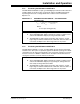
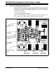
2.2 PCB DESCRIPTION
The MCP402X Digital Potentiometer Evaluation Board has the following features:
• 150 mil, 8-pin SOIC pinout (U1) supports the MCP4021 and MCP4011 devices
• SOT-23-6 pinout (U2) supports the MCP4022/23/24 and MCP4012/13/14 devices
• SOT-23-6 pinout (U3) supports the PIC10F20X devices
• Connection terminals can be left unpopulated for easy connection using small
alligator clip leads (clamped across the edge of the board) or populated with either
through-hole or surface-mount terminals
• Footprints for optional passive components for:
- Power supply filtering
- Device bypass capacitor
- Terminal “A” pull-up resistor
- Terminal “B” pull-down resistor
• Footprints for two switches:
- INCR button operation can be detected by the PIC10F20X to generate
Increment commands (move wiper toward terminal A)
- DECR button operation can be detected by the PIC10F20X to generate
Decrement commands (move wiper toward terminal B)
• Button sequence instructions are printed on the back of the PCB
Appendix A.2 “Schematic” illustrates the schematic for the MCP402XEV.
Note: The PIC10F20X firmware (00066_MCP402XEV.HEX) must be
programmed into the microcontroller before the MCP402XEV is functional.