
User manual

MCP3905A/06A Energy Meter Reference Design
DS51565B-page 8 © 2009 Microchip Technology Inc.
2.3 GETTING STARTED
This meter can be manufactured by performing the following two steps detailed in this
document. For the external connections, the following terms are used: “phase” refers
to the hot (or line) side of the power supply lines. “Neutral” refers to the return wire
(or low-side) of the power supply lines.
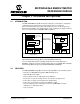
2.3.1 External Connections
Connections are made to the phase and neutral wire for voltage-detection and AC/DC
power supply. The MCP3905A/06A Energy Meter Reference Design is designed to be
biased to the phase (or hot) side of a 2-wire power supply system.
1. Connect JP4 to the phase power supply line connection.
2. Connect JP3 to the neutral line.
3. Connect JP1 and JP2 across the shunt.
4. Connect JP5 and JP6 to the mechanical counter.
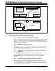
2.3.2 Calibration of the Frequency Output using the Voltage Divider
Calibration Circuit
Each meter must be calibrated using the voltage divider circuit going into Channel 1 of
the MCP3905A/06A. A known power is supplied to the meter (e.g., 1000W), and an
expected output frequency is the goal (1000 imp/kWh). Start with the highest value
resistor and short the resistor using it's respective shorting jumper. If the output
frequency is too high, remove the shunt. Continue testing each resistor short until all
jumpers are tested once. For more detailed information regarding meter calibration and
the PCB design approach using the circuitry in this document, refer to AN994,
“IEC Compliant Active Energy Meter Design Using The MCP3905A/06A” (DS00994).
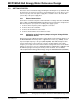
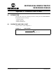
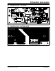
FIGURE 2-2: Photograph of Complete, Stand-Alone MCP3905A Energy Meter.