MCP3905A/06A Energy Meter Reference Design © 2009 Microchip Technology Inc.
Note the following details of the code protection feature on Microchip devices: • Microchip products meet the specification contained in their particular Microchip Data Sheet. • Microchip believes that its family of products is one of the most secure families of its kind on the market today, when used in the intended manner and under normal conditions. • There are dishonest and possibly illegal methods used to breach the code protection feature.
MCP3905A/06A ENERGY METER REFERENCE DESIGN Table of Contents Preface ........................................................................................................................... 1 Chapter 1. Product Overview 1.1 Introduction ..................................................................................................... 5 1.2 What is the MCP3905A/06A Energy Meter Reference Design? .................... 5 1.3 What the MCP3905A/06A Energy Meter Reference Design Kit Includes ......
MCP3905A/06A Energy Meter Reference Design NOTES: DS51565B-page iv © 2009 Microchip Technology Inc.
MCP3905A/06A ENERGY METER REFERENCE DESIGN Preface NOTICE TO CUSTOMERS All documentation becomes dated, and this manual is no exception. Microchip tools and documentation are constantly evolving to meet customer needs, so some actual dialogs and/or tool descriptions may differ from those in this document. Please refer to our web site (www.microchip.com) to obtain the latest documentation available. Documents are identified with a “DS” number.
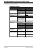
MCP3905A/06A Energy Meter Reference Design CONVENTIONS USED IN THIS GUIDE This manual uses the following documentation conventions: DOCUMENTATION CONVENTIONS Description Arial font: Italic characters Represents Referenced books Emphasized text A window A dialog A menu selection A field name in a window or dialog A menu path MPLAB® IDE User’s Guide ...is the only compiler...
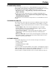
Preface RECOMMENDED READING This user's guide describes how to use MCP3905A/06A Energy Meter Reference Design. Other useful documents are listed below. The following Microchip documents are available and recommended as supplemental reference resources. • MCP3905 Data Sheet, “Energy Metering IC with Active Real Power Pulse Output” (DS21948) This data sheet provides detailed information regarding the MCP3905A device.
MCP3905A/06A Energy Meter Reference Design DOCUMENT REVISION HISTORY Revision B (August 2009) • Update from MCP3905/06 to MCP3905A/06A devices Revision A (July 2005) • Initial Release of this Document DS51565B-page 4 © 2009 Microchip Technology Inc.
MCP3905A/06A ENERGY METER REFERENCE DESIGN Chapter 1. Product Overview 1.1 INTRODUCTION This chapter provides an overview of the MCP3905A/06A Energy Meter Reference Design and covers the following topics: • What is the MCP3905A/06A Energy Meter Reference Design? • What the MCP3905A/06A Energy Meter Reference Design Kit includes 1.
MCP3905A/06A Energy Meter Reference Design NOTES: DS51565B-page 6 © 2009 Microchip Technology Inc.
MCP3905A/06A ENERGY METER REFERENCE DESIGN Chapter 2. Installation and Operation 2.1 INTRODUCTION The MCP3905A/06A Energy Meter Reference Design is a stand-alone, single-phase residential meter design for active-energy meter designs. For advanced microcontroller-based meter products, this design also serves as the design of the Analog Front-End (AFE). This design includes a low-cost DC power supply circuit and the necessary protection for IEC62053 EMC compliance.
MCP3905A/06A Energy Meter Reference Design 2.3 GETTING STARTED This meter can be manufactured by performing the following two steps detailed in this document. For the external connections, the following terms are used: “phase” refers to the hot (or line) side of the power supply lines. “Neutral” refers to the return wire (or low-side) of the power supply lines. 2.3.1 External Connections Connections are made to the phase and neutral wire for voltage-detection and AC/DC power supply.
Installation and Operation 2.4 ENERGY METER REFERENCE DESIGN OVERVIEW This reference design can be used as either a stand-alone mechanical counter energy meter, or as the analog front-end design in advanced microcontroller-based meter designs. The AFE design limits the overall meter accuracy. A low noise, proven AFE circuit and layout is still required for a high-accuracy meter.
MCP3905A/06A Energy Meter Reference Design Output Connections (JP5-JP7) Shunts for Gain, FC and HPF Selection (J11-J15) Power Supply Ground Plane Analog Ground Plane Voltage Conn. (JP3,JP4) Current Conn. Calibration (JP1,JP2) Jumpers (J1-J10) FRONT MCP3905A (U1) Opto. Isolator (U3) DC Power Supply MOV1 Power Supply Ground Plane Analog Ground Plane BACK FIGURE 2-3: 2.5 MCP3905A/06A Energy Meter Reference Design Block Diagram. FRONT-SIDE OF PCB DETAILED DESCRIPTION 2.5.
Installation and Operation 2.5.5 Connection to Voltage or Phase Line and Ground Reference Point (JP3,JP4) These two connections feed the DC power supply circuitry described in Section 2.6.3 “Metal Oxide Varistor (MOV1)”. JP4 is connected to the ground of the PCB, and JP3 to the high-side of the DC power supply circuitry. JP3 is also connected to the resistor divider that feeds the analog input of Channel 1 of the MCP3905A/06A.
MCP3905A/06A Energy Meter Reference Design NOTES: DS51565B-page 12 © 2009 Microchip Technology Inc.
MCP3905A/06A ENERGY METER REFERENCE DESIGN Appendix A. Schematics and Layouts A.1 INTRODUCTION This appendix contains the following schematics and layouts for the MCP3905A/06A Energy Meter Reference Design: • Board Schematic • Board – Top Layer • Board – Bottom Layer A.2 SCHEMATICS AND PCB LAYOUT The layer order is shown in Figure A-1. FIGURE A-1: LAYER ORDER Top Layer Bottom Layer © 2009 Microchip Technology Inc.
A B C Z1 JP4 1 0.01uF C16 110 Ohms at 100MHz JP3 150K R6 R5 300K 0 Ohms 0 Ohms 1N4744A 1N4004 D2 R21 470 Ohms C17 0.47uF R16 330K R15 330K J2 D3 R2 2 75K R7 0 Ohms J3 470uF/35V C18 8 1K C2 VIN R4 1K R3 7805 39K R8 0 Ohms J4 C3 VOUT 1 Z2 VDD 0.1uF C6 VDD 1 2 3 4 5 6 7 8 9 10 11 12 9.1K R10 0 Ohms J6 C5 10uF/6.3V MCP3905-SSOP24 24 23 22 21 20 19 18 17 16 15 14 13 5.
Schematics and Layouts A.4 BOARD LAYOUT – TOP LAYER A.5 BOARD LAYOUT – BOTTOM LAYER © 2009 Microchip Technology Inc.
MCP3905A/06A Energy Meter Reference Design NOTES: DS51565B-page 16 © 2009 Microchip Technology Inc.
MCP3905A/06A ENERGY METER REFERENCE DESIGN Appendix B. Bill Of Materials (BOM) TABLE B-1: Qty BILL OF MATERIALS (BOM) Reference Description Manufacturer Part Number 4 C1, C2, C3, C4 CAP 33000PF 50V CERM X7R 0805 Panasonic® - ECG ECJ-2VB1H333K 2 C5, C13 CAPACITOR TANT 10UF 6.3V 20% SMD Kemet® Electronics Corp. T491A106M006AS 6 C6, C7, C10, C12, C14,C15 CAP .
MCP3905A/06A Energy Meter Reference Design TABLE B-1: Qty BILL OF MATERIALS (BOM) (CONTINUED) Reference Description Manufacturer Part Number 1 R14 RES 560 OHM 1/16W 5% 0402 SMD Panasonic - ECG ERJ-2GEJ561X 2 R15, R16 RES 330K OHM 1/2W 5% 2010 SMD Panasonic - ECG ERJ-12ZYJ334U 1 R18 RES 820 OHM 1/4W 5% 1206 SMD Panasonic - ECG ERJ-8GEYJ821V 2 R19, R20 RES 20 OHM 1/4W 5% 1206 SMD Panasonic - ECG ERJ-8GEYJ200V 1 R21 RES 470 OHM 1W 5% METAL OXIDE Panasonic - ECG ERG-1SJ471 1 R22
Bill Of Materials (BOM) NOTES: © 2009 Microchip Technology Inc.
WORLDWIDE SALES AND SERVICE AMERICAS ASIA/PACIFIC ASIA/PACIFIC EUROPE Corporate Office 2355 West Chandler Blvd. Chandler, AZ 85224-6199 Tel: 480-792-7200 Fax: 480-792-7277 Technical Support: http://support.microchip.com Web Address: www.microchip.