
User manual


Firmware
2010 Microchip Technology Inc. DS51845B-page 17
When the first sample is written in the buffer, the 32-bit timer created using Timer8 and
9, begins counting from 0. When the last sample is written into the buffer, the 32-bit
timer is read. The value indicated will be used to compute the sampling speed.
If the CCT is 1, then the data read from the MCP3901 will be the configuration data.
This will be saved in MCU in other global variables, used later to send this info to the
PC GUI.
After the SPI communication completes, the SPI interrupt will be disabled and the
UART TX interrupt will be enabled. The first character sent on UART is char 33; this is
the header of the UART communication protocol that is adopted here.
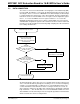
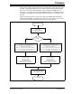
FIGURE 2-2: SPI Routine Flowchart.
SPI1 Transfer Interrupt
Clear Flag;
Read SPI1BUF;
Read Address Loop Bits from
If Address Loop =
NONE?
Send 12 transfers on the SPI to read the content of the 6
registers that are holding the ADC result;
Compute the 24-bit value for each channel and save it in
voltage and current buffers;
At the first sample, read start timer 32-bit Timer8:9;
At the read of the last sample, read the Timer8:9 content
(for sampling speed measurement)
Send 6 transfers on the SPI to read the content of the 6
registers that are holding the ADC result;
Compute the 24-bit value for each channel and save it in
voltage and current buffers;
At the first sample read, start timer 32-bit Timer8:9;
At the read of the last sample, read the Timer8:9 content
(for sampling speed measurement)
YES NO
Read Modulator Output register;
Read Phase register;
Read Gain register;
Read Status register;
Read Configuration High register;
Read Configuration Low register
Read Modulator Output register;
Read Phase register;
Read Gain register;
Read Status register;
Read Configuration High register;
Read Configuration Low register
Disable SPI interrupt;
Enable UART TX interrupt;
Sent the char 0d33 on UART
Exit SPI Interrupt
Status Registr