
User manual


Hardware Description
2010 Microchip Technology Inc. DS51845B-page 11
1.2 PIM MODULE/MCP3901 CONNECTION AND PERIPHERAL USAGE
OVERVIEW
The MCP3901 ADC Evaluation Board for 16-Bit MCUs contains a 100-pin PIM socket
compatible with Microchip’s PIM modules. The system comes with 2 PIM modules: the
PIC24FJ128GA010 and dsPIC33FJ256GA710.
A complete description of the firmware programmed with these two modules is
available in Chapter 1. “Hardware Description”.
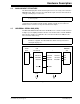
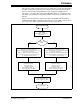
FIGURE 1-2: Digital Connection Overview PIM/MCP3901 Connections.
Ports A, B, and D are used for signals such as push buttons, output LEDs, CS
and
MCLR
(for MCP3901 data mode setting). Output Capture 1 is used for MCP3901’s
clock generation. Serial communication is achieved through the MSSP module 1.
CONTROL SWITCHES (X3)
CH0+
CH0-
CH1+
CH1-
AVDD
AGND
OSC1
MCP3901
MDAT0
SDI
SDO
RA5
RA4
SCK1/RF6
SDO1/RF8
SDI1/RF7
RB8/9/10
PIM Module
SCK
OSC2
OC1/RD0
RA9/10
D6 D7
(Green)
RF3/U1TX
RF2/U1RX
UART SERIAL TO PC COMMUNICATION
MDAT1
RESET
DR
CS
SPI Serial
Interface
Delta Sigma
Multi-Level
Modulator
Delta Sigma
Multi-Level
Modulator
PGA
PGA
+
+
-
-
INT
V
REF
Clock Generation/
Phase Correction
Current Boost
Circuit
Modulator
Output
Translation
Block
SINC3
Digital Filter
SINC3
Digital Filter
DGND DVDD
INT3/RA4
IC4/RD11
IC3/RD10