MCP3901 ADC Evaluation Board for 16-Bit MCUs User’s Guide 2010 Microchip Technology Inc.
Note the following details of the code protection feature on Microchip devices: • Microchip products meet the specification contained in their particular Microchip Data Sheet. • Microchip believes that its family of products is one of the most secure families of its kind on the market today, when used in the intended manner and under normal conditions. • There are dishonest and possibly illegal methods used to breach the code protection feature.
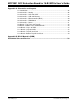
MCP3901 ADC EVALUATION BOARD FOR 16-BIT MCUs USER’S GUIDE Table of Contents Preface ........................................................................................................................... 5 Introduction............................................................................................................ 5 Document Layout .................................................................................................. 5 Conventions Used in this Guide ...............................
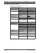
MCP3901 ADC Evaluation Board for 16-Bit MCUs User’s Guide Appendix A. Schematics and Layouts A.1 Introduction .................................................................................................. 25 A.2 Schematic – Analog ..................................................................................... 26 A.3 Schematic – LCD and UART ...................................................................... 27 A.4 Schematic – USB and Memory ......................................................
MCP3901 ADC EVALUATION BOARD FOR 16-BIT MCUs USER’S GUIDE Preface NOTICE TO CUSTOMERS All documentation becomes dated, and this manual is no exception. Microchip tools and documentation are constantly evolving to meet customer needs, so some actual dialogs and/or tool descriptions may differ from those in this document. Please refer to our web site (www.microchip.com) to obtain the latest documentation available. Documents are identified with a “DS” number.
MCP3901 ADC Evaluation Board for 16-Bit MCUs User’s Guide CONVENTIONS USED IN THIS GUIDE This manual uses the following documentation conventions: DOCUMENTATION CONVENTIONS Description Arial font: Italic characters Initial caps Quotes Underlined, italic text with right angle bracket Bold characters N‘Rnnnn Text in angle brackets < > Courier New font: Plain Courier New Represents Referenced books Emphasized text A window A dialog A menu selection A field name in a window or dialog A menu path MPLAB® IDE
Preface RECOMMENDED READING This user's guide describes how to use MCP3901 ADC Evaluation Board for 16-Bit MCUs. Other useful documents are listed below. The following Microchip document is available and recommended as supplemental reference resources: MCP3901 Data Sheet - “Two Channel Delta Sigma A/D Converter”, DS22192 THE MICROCHIP WEB SITE Microchip provides online support via our web site at www.microchip.com.
MCP3901 ADC Evaluation Board for 16-Bit MCUs User’s Guide NOTES: DS51845B-page 8 2010 Microchip Technology Inc.
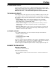
MCP3901 ADC EVALUATION BOARD FOR 16-BIT MCUs USER’S GUIDE Chapter 1. Hardware Description 1.1 OVERVIEW The MCP3901 ADC Evaluation Board for 16-Bit MCUs system provides the ability to evaluate the performance of the MCP3901 dual channel ADC. It also provides a development platform for 16-bit PIC® MCU-based applications, using existing 100-pin Plug-in Module (PIM) systems compatible with the Explorer 16 and other high pin count PIC MCU demo boards.
MCP3901 ADC Evaluation Board for 16-Bit MCUs User’s Guide CH0+ GND CH0- G CH1+ GND CH1- + MCP3901 G - + - + - EXT +5V Serial Connector EXT +5V +9V IN USB PIM RESET MCP3901 Digital I/O SW2 SW3 SW4 RA9 USB +3V REG PWR LED (Blue) PIC18F86J65 PIC18 AUX I/O SRAM PICtail™ Plus PIC18 ICD PIC18 ICD 9V EXT. IN +5V REG RA10 PIM (100-PIN) PIC18 EXTERNAL I/O MCP3901 ADC Evaluation Board for 16-Bit MCUs FIGURE 1-1: DS51845B-page 10 MCP3901 ADC Evaluation Board for 16-Bit MCUs.
Hardware Description 1.2 PIM MODULE/MCP3901 CONNECTION AND PERIPHERAL USAGE OVERVIEW The MCP3901 ADC Evaluation Board for 16-Bit MCUs contains a 100-pin PIM socket compatible with Microchip’s PIM modules. The system comes with 2 PIM modules: the PIC24FJ128GA010 and dsPIC33FJ256GA710. A complete description of the firmware programmed with these two modules is available in Chapter 1. “Hardware Description”.
MCP3901 ADC Evaluation Board for 16-Bit MCUs User’s Guide 1.3 MCP3901 DELTA-SIGMA SAMPLING/MCLK OPTIONS The MCP3901 device is an ADC with a second order modulator and a third order sync filter. This Delta-Sigma A/D converter has an adjustable oversampling ratio. The CLKIN pin of the MCP3901 is the oversampling clock (MCLK) input. The MCP3901 ADC Evaluation Board for 16-Bit MCUs offers two different options for the MCP3901 master clock (MCLK). 1.3.
Hardware Description 1.4 ANALOG INPUT STRUCTURE Two differential input paths allow external signal sources to be easily connected to the MCP3901 input. Edge connectors JP1 and JP2 are 3-pin connectors that act both as crew type and clip on post connectors. Note: To use an edge connector as a post connector, pull up the blue plastic top to access posts. JP1 and JP2 can be used to force either channel from a differential to single-ended configuration.
MCP3901 ADC Evaluation Board for 16-Bit MCUs User’s Guide NOTES: DS51845B-page 14 2010 Microchip Technology Inc.
MCP3901 ADC EVALUATION BOARD FOR 16-BIT MCUs USER’S GUIDE Chapter 2. Firmware 2.1 DSPIC33 FIRMWARE DESCRIPTION 2.1.1 Reset and Initialization After reset, the global variables ConfigHValue, ConfigLValue, GainValue, and StatusComValue are written to 0x00. These variables will be written with values received from the PC, to set up the MCP3901 as required. Next, the Initialization() function is called to set up the dsPIC33.
MCP3901 ADC Evaluation Board for 16-Bit MCUs User’s Guide 2.2 DATA ACQUISITION The end of a conversion is indicated with a short high pulse on the Data Ready (DR) pin of the ADC. The DR pin is connected to the External Interrupt 3 pin and is used for detecting the end of a conversion on MCP3901. In the INT3 interrupt, the SPI interrupt is activated and the first transmission on the SPI is initiated.
Firmware When the first sample is written in the buffer, the 32-bit timer created using Timer8 and 9, begins counting from 0. When the last sample is written into the buffer, the 32-bit timer is read. The value indicated will be used to compute the sampling speed. If the CCT is 1, then the data read from the MCP3901 will be the configuration data. This will be saved in MCU in other global variables, used later to send this info to the PC GUI.
MCP3901 ADC Evaluation Board for 16-Bit MCUs User’s Guide 2.3 UART COMMUNICATION PROTOCOL The MCU uses the UART to send and receive data to the PC. The TX and RX interrupts are not used simultaneously in this firmware example, but it is possible to do so, if the user requires it. As soon as the buffer is filled with data from the ADC, the SPI interrupt is disabled, and the TX interrupt is enabled. There are more types of data to be sent from the MCU to the PC.
Firmware UART TX Interrupt contrd<=512? NO YES Get CH0 sample from current[contrd]; Change Long into 8 digit string; write character “,” to val[8]; Get CH1 samples from voltage[contrd]; Change the value in 8 digit string; Write char CR to val[17] contrd=513? NO YES Send char “D”; Increment contrd NO contrd2<=17? NO contrd=514? YES YES contrd2=0; Increment contrd Send val[contrd2]; Increment contrd2 NO contrd=515? YES NO Contrd==515+ REAL_N+1? YES Contrd<=515+REAL_N? YES Transform the FFT
MCP3901 ADC Evaluation Board for 16-Bit MCUs User’s Guide NOTES: DS51845B-page 20 2010 Microchip Technology Inc.
MCP3901 ADC EVALUATION BOARD FOR 16-BIT MCUs USER’S GUIDE Chapter 3. MCP3901 PC Software Tool 3.1 SOFTWARE OVERVIEW The MCP3901 ADC Evaluation Board for 16-Bit MCUs includes a PC Graphical User Interface (GUI) that performs: • ADC configuration • Data analysis for easier system debugging • Device evaluation Figure 3-1 shows a sample of the software’s GUI. FIGURE 3-1: MCP3901 Data View Interface. 2010 Microchip Technology Inc.
MCP3901 ADC Evaluation Board for 16-Bit MCUs User’s Guide 3.2 SETTING THE CONFIGURATION OF THE ADC The MCP3901 Data View sets up the configuration registers of the MCP3901 by putting the desired value on the “Write Registers” tab. Usually, it takes a few seconds to update the MCP3901 configuration. To learn the configuration of the MCP3901 without changing it, click on the “Read Registers” tab and the same image as in “Write Registers” will display.
MCP3901 PC Software Tool Use Equation 3-2 if the data is represented on 24 bits. EQUATION 3-2: ENOB = 24 – log 2 ENOB can also be computed when an AC signal is applied at the input. The formula to compute ENOB in an AC case is shown in Equation 3-3. EQUATION 3-3: SINAD – 1.76 ENOB = ---------------------------------6.02 The distribution of noise from the acquired signal displays on the Histogram Graph screens.These graphs indicate how many times a code was present inside a buffer. 3.
MCP3901 ADC Evaluation Board for 16-Bit MCUs User’s Guide NOTES: DS51845B-page 24 2010 Microchip Technology Inc.
MCP3901 ADC EVALUATION BOARD FOR 16-BIT MCUs USER’S GUIDE Appendix A. Schematics and Layouts A.1 INTRODUCTION This appendix contains the following schematics and layouts of the MCP3901 ADC Evaluation Board for 16-Bit MCUs.
MCP3901 ADC Evaluation Board for 16-Bit MCUs User’s Guide SCHEMATIC – ANALOG M A.2 DS51845B-page 26 2010 Microchip Technology Inc.
Schematics and Layouts SCHEMATIC – LCD AND UART M A.3 2010 Microchip Technology Inc.
MCP3901 ADC Evaluation Board for 16-Bit MCUs User’s Guide SCHEMATIC – USB AND MEMORY M A.4 DS51845B-page 28 2010 Microchip Technology Inc.
Schematics and Layouts SCHEMATIC – MICROCONTROLLER (MCU) M A.5 2010 Microchip Technology Inc.
MCP3901 ADC Evaluation Board for 16-Bit MCUs User’s Guide SCHEMATIC – PIM MODULE M A.6 DS51845B-page 30 2010 Microchip Technology Inc.
Schematics and Layouts SCHEMATIC – POWER M A.7 2010 Microchip Technology Inc.
MCP3901 ADC Evaluation Board for 16-Bit MCUs User’s Guide A.8 BOARD – TOP TRACE AND TOP SILK MCP3901 ADC Eval Board for 16-bit MCU A.9 BOARD – BOTTOM TRACE AND BOTTOM SILK DS51845B-page 32 2010 Microchip Technology Inc.
Schematics and Layouts A.10 BOARD – LAYER #2 VDD A.11 BOARD – LAYER #3 GND 2010 Microchip Technology Inc.
MCP3901 ADC Evaluation Board for 16-Bit MCUs User’s Guide A.12 BOARD – TOP SILK AND PADS MCP3901 ADC Eval Board for 16-bit MCU A.13 BOARD – BOTTOM TOP SILK AND PADS DS51845B-page 34 2010 Microchip Technology Inc.
MCP3901 ADC EVALUATION BOARD FOR 16-BIT MCUs USER’S GUIDE Appendix B. Bill Of Materials (BOM) TABLE B-1: Qty BILL OF MATERIALS Reference Description Manufacturer ® Part Number 30 C11<>C22 CAP CER .1UF 25V 10% X7R 0603 Murata Electronics C24<>C30 C33, C34, C35, C36, C39, C40, C43 C47, C48, C49 C50 GRM188R71E104KA01D 2 C2, C6 CAP CER 4.
MCP3901 ADC Evaluation Board for 16-Bit MCUs User’s Guide TABLE B-1: Qty BILL OF MATERIALS (CONTINUED) Reference Description Manufacturer Part Number 1 L1 Shielded 10uH Power Inductor 0805 Coilcraft 0805PS-103KLC 1 LCD2 16X2 FTN Reflective No. BLWT COG 3V TianMa TM162JCAWG1 4 MOD1 25 X 1 Header 1.27mm on center SAMTEC MTMS-125-01-G-S-230 1 P1, P2 CONN TERM BLK PLUG 6A 3.5MM 3POS Keystone Electronics 8723 1 P3 CONN TERM BLK PLUG 6A 3.
Bill Of Materials (BOM) TABLE B-1: Qty BILL OF MATERIALS (CONTINUED) Reference Description Manufacturer Part Number 1 TP1 Wire Test Point 0.3" Length 1 U1 IC REG LDO 800MA 5.0V SOT-223 National Semiconductor LM1117MP-5.0/NOPB 1 U2 IC PIC USB MCU FLASH 48KX16 80TQFP PIC18F86J55-I/PT 1 U3 IC REG LDO 800MA 3.3V SOT-223 National Semiconductor® LM1117MP-3.3/NOPB 1 U4 IC ENERGY METER 24SSOP Microchip Technology Inc.
Worldwide Sales and Service AMERICAS ASIA/PACIFIC ASIA/PACIFIC EUROPE Corporate Office 2355 West Chandler Blvd. Chandler, AZ 85224-6199 Tel: 480-792-7200 Fax: 480-792-7277 Technical Support: http://support.microchip.com Web Address: www.microchip.