
Datasheet

MCP3901 Low-Cost Power Monitor Reference Design
DS51915A-page 18 2010 Microchip Technology Inc.
2.2 CALIBRATION PROCEDURE
The power monitor should be calibrated to provide accurate measurements. Due to the
implemented signal processing technique, a single-point calibration is sufficient.
To achieve power factor compensations without modifying the hardware, the phase
delay block in the MCP3901 power monitor reference design is used. Through having
written a correct value in the Phase Delay register, one channel sample is delayed rel-
ative to the other channel sample.
Most of the phase errors are caused by phase delays induced by the various compo-
nents of the meter (i.e., RC filters, current transformers, etc.), from one of the two chan-
nels. This block can induce an extra phase delay on the other channel, so the phase
delay is compensated, and measurement errors caused by power factor variations are
decreased.
The correct value for the Phase Delay register is determined automatically during the
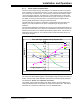
calibration routine using the following method. First, determine the influence of the
Phase Delay register (kk) over measurement variation for the design. Five points are
enough to see a linear dependency, and by choosing the best fit, the Power Factor
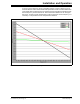
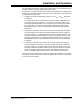
compensation equation is obtained, as shown in Figure 2-8:
FIGURE 2-8: Influence of the Phase Delay Register Over Measurement
Accuracy at Different Phase Angles.
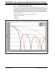
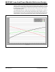
The measurement variation is, in fact, the variation of the indication for the Active
Power value at 45 degrees and -45 degrees. These two points were chosen because
the measurement indication is varying almost linearly in this interval, as shown in
Figure 2-3.
Power Factor Compensation Equation
y = 4.9693x - 0.9836
-4
-3
-2
-1
0
1
2
-0.6 -0.4 -0.2 0 0.2 0.4 0.6
Measurement Variation (%)
Phase Delay Register (kk)
Measurements
Linear Best Fit