
Datasheet


MCP3901 Low-Cost Power Monitor Reference Design
DS51915A-page 12 2010 Microchip Technology Inc.
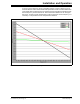
Because the offset is removed and the rest of the system has a linear response, a
single point calibration method is sufficient to obtain accurate readings.
To compute the instantaneous active power, samples of the current and voltage are
multiplied. To extract the average active power, the instantaneous active power
samples are filtered by two first-order Infinite Impulse Response low-pass filters (IIR
LPF). To obtain the values for the U
RMS
and I
RMS
, the acquired samples are multiplied
to extract the instantaneous U
2
and I
2
. For the integrated values, the samples go
through the second first-order IIR LPF. To obtain a value proportional with I
RMS
, a
square root operation (SQRT) is performed.
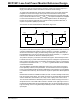
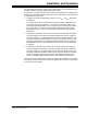
The structure of a first-order IIR filter is illustrated in Figure 2-2.
FIGURE 2-2: First-Order IIR Filter Structure.
The power monitor also has a pulse output for energy measurements and an extra cir-
cuit that is implemented to perform a power-to-frequency conversion. In addition, a
24-bit timer is included to supply accurate timings of the pulse output. Because the
PIC18F25K20 MCU only has a 16-bit timer, a 8-bit Timer0 extended (t0e) register is
included in the software to obtain the desired pulse period.
The power-to-frequency conversion is achieved through the Timer0 interrupt routine.
For better accuracy in power measurement, the power is averaged for a period of time
that is equal to the pulse output. The resulting averaged power value is converted into
three bytes that are written to the t0l, t0h, and t0e global variables. These variables
control the 24-bit timer.
The LCD displays the important parameters U
RMS
, I
RMS
, Power Factor, and Active
Power (default). However, more parameters, such as Reactive Power and Apparent
Power, can be displayed with minimum modifications of the firmware. The LCD display
is controlled in the main loop, since it does not require an update at a definite period of
time.
Measurement results are available via UART, as well – the MCU steadily sends U
RMS
,
I
RMS
and Active Power values. The UART connection is configured with the following
values: 19200 baud, 8-bit of data, 1-bit of stop, none of parity, and no flow control.
The connection between the MCP3901 power monitor reference design and a PC is
simple and secure. The UART-USB converter is located on the upper-right corner of
the PCB and implemented via U4 (PIC18F14K50). And, to prevent exposing the PC to
high-risk voltage, the circuit is galvanically isolated by the rest of the meter through an
optocoupler.
x[n]
b
0
b
1
z
-1
z
-1
v[n]
y[n]
a
1
y[n-1]