MCP3901 Low-Cost Power Monitor Reference Design User’s Guide 2010 Microchip Technology Inc.
Note the following details of the code protection feature on Microchip devices: • Microchip products meet the specification contained in their particular Microchip Data Sheet. • Microchip believes that its family of products is one of the most secure families of its kind on the market today, when used in the intended manner and under normal conditions. • There are dishonest and possibly illegal methods used to breach the code protection feature.
MCP3901 LOW-COST POWER MONITOR USER’S GUIDE Table of Contents Preface ........................................................................................................................... 5 Introduction............................................................................................................ 5 Document Layout .................................................................................................. 5 Conventions Used in this Guide .............................................
MCP3901 Low-Cost Power Monitor User’s Guide NOTES: DS51915A-page 4 2010 Microchip Technology Inc.
MCP3901 LOW-COST POWER MONITOR REFERENCE DESIGN Preface NOTICE TO CUSTOMERS All documentation becomes dated, and this manual is no exception. Microchip tools and documentation are constantly evolving to meet customer needs, so some actual dialogs and/or tool descriptions may differ from those in this document. Please refer to our web site (www.microchip.com) to obtain the latest documentation available. Documents are identified with a “DS” number.
MCP3901 Low-Cost Power Monitor Reference Design CONVENTIONS USED IN THIS GUIDE This manual uses the following documentation conventions: DOCUMENTATION CONVENTIONS Description Arial font: Italic characters Initial caps Quotes Underlined, italic text with right angle bracket Bold characters N‘Rnnnn Text in angle brackets < > Courier New font: Plain Courier New Represents Referenced books Emphasized text A window A dialog A menu selection A field name in a window or dialog A menu path MPLAB® IDE User’s Gui
Preface RECOMMENDED READING This user's guide describes how to use the MCP3901 Low-Cost Power Monitor Reference Design. Other useful documents are listed below. The following Microchip documents are available and recommended as supplemental reference resources.
MCP3901 Low-Cost Power Monitor Reference Design NOTES: DS51915A-page 8 2010 Microchip Technology Inc.
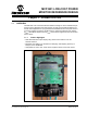
MCP3901 LOW-COST POWER MONITOR REFERENCE DESIGN Chapter 1. Product Overview 1.1 OVERVIEW The MCP3901 Low-Cost Power Monitor Reference Design is used to evaluate the performance of the MCP3901 dual channel ADC, as well as a development platform for PIC18F-based applications. A programmed PIC18F25K20 device in the power monitor processes samples acquired by the MCP3901 to obtain Root Mean Square Voltage (URMS), Root Mean Square Current (IRMS), Active Power, Apparent Power, and Power Factor values. 1.1.
MCP3901 Low-Cost Power Monitor Reference Design 1.2 ANALOG INPUT CIRCUIT The MCP3901 Low-Cost Power Monitor Reference Design uses an MCP3901 dual ADC to acquire current and voltage samples. For best performance, the power supply and ground must be noise free. To ensure low noise, large capacitors are located on the lines that power the MCP3901 device, i.e., C4 and C5.
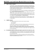
MCP3901 LOW-COST POWER MONITOR REFERENCE DESIGN Chapter 2. Installation and Operation 2.1 POWER MONITOR FIRMWARE DESCRIPTION 2.1.1 Samples Acquisition Using the external ADC, the current and voltage samples must be acquired before the correct values of the desired parameters can be computed. The MCU reads the values of the samples from the ADC through the SPI bus. The sampling speed of the ADC is controlled by the clock frequency of the MCP3901.
MCP3901 Low-Cost Power Monitor Reference Design Because the offset is removed and the rest of the system has a linear response, a single point calibration method is sufficient to obtain accurate readings. To compute the instantaneous active power, samples of the current and voltage are multiplied. To extract the average active power, the instantaneous active power samples are filtered by two first-order Infinite Impulse Response low-pass filters (IIR LPF).
Installation and Operation 2.1.3 Power Factor Compensation One of the major tasks in energy meter design is to minimize the effect of the power factor variations on measurement accuracy. In order to have accurate measurements over a wide range of power factors, it is necessary to have the same delays on both current and voltage channels.
MCP3901 Low-Cost Power Monitor Reference Design 2.1.4 Line Frequency Compensation A 50 Hz line frequency is used, which is the typical frequency most of the time. However, this is not a constant and can vary above or below this value by a few Hertz. This line frequency shift can cause measurement errors because of the characteristics of the Sinc filter at low sampling speeds. The Sinc filter transfer function is similar to a low-pass filter.
Installation and Operation In Figure 2-5, the frequency range is magnified and the Y axis is scaled to cross at 50 Hz for all three cases. Notice that the low speed ADC causes a sensitive attenuation of the signal when the line frequency is higher than 50 Hz compared to situations when the line frequency is lower than 50 Hz. The measurement differences can be higher than 0.2%.
MCP3901 Low-Cost Power Monitor Reference Design Although complex, long, finite impulse response (FIR) structures called Sinc Compensation Filters are usually used to compensate for low-pass filter difficulties, they cannot be implemented in this application because the MCU is being used at close to maximum computation power.
Installation and Operation Error (%) Figure 2-7 illustrates the error measurements in the frequency range of 48-52 Hz at 5 ARMS current. 0.1 0.08 0.06 0.04 0.02 0 -0.02 47 -0.04 -0.06 -0.08 -0.1 Error vs frequency 48 49 50 51 52 53 Frequency Line (Hz) FIGURE 2-7: Errors vs. Line Frequency. Line frequency compensation is a simplified solution and does not compensate for frequencies in which harmonics exist. However, it significantly improves the overall accuracy of the meter.
MCP3901 Low-Cost Power Monitor Reference Design 2.2 CALIBRATION PROCEDURE The power monitor should be calibrated to provide accurate measurements. Due to the implemented signal processing technique, a single-point calibration is sufficient. To achieve power factor compensations without modifying the hardware, the phase delay block in the MCP3901 power monitor reference design is used.
Installation and Operation The appropriate Phase Delay register value is determined by the measurement of the indication variation during the following calibration routine. As calibration is initiated, the values of the Active Power Scaling Factor, RMS Current Scaling Factor, and RMS Voltage Scaling Factor at a Power Factor of 1 are determined through the following process: 1.
MCP3901 Low-Cost Power Monitor Reference Design NOTES: DS51915A-page 20 2010 Microchip Technology Inc.
MCP3901 LOW-COST POWER MONITOR REFERENCE DESIGN Appendix A. Schematics and Layouts This appendix contains the following schematics of the MCP3901 Low-Cost Power Monitor Reference Design. • • • • • Board Schematic – Analog and Power Board Schematic – Microcontroller and LCD Board Schematic – Universal Serial Bus Board – Top Trace and Top Silk Board – Bottom Trace and Bottom Silk 2010 Microchip Technology Inc.
MCP3901 Low-Cost Power Monitor Reference Design A.1 BOARD SCHEMATIC – ANALOG AND POWER DS51915A-page 22 2010 Microchip Technology Inc.
Schematics and Layouts A.2 BOARD SCHEMATIC – MICROCONTROLLER AND LCD 2010 Microchip Technology Inc.
MCP3901 Low-Cost Power Monitor Reference Design A.3 BOARD SCHEMATIC – UNIVERSAL SERIAL BUS DS51915A-page 24 2010 Microchip Technology Inc.
Schematics and Layouts A.4 BOARD – TOP TRACE AND TOP SILK DANGER HIGH VOLTAGE MCP A.5 3901 PIC18F25K20 POWER METER BOARD – BOTTOM TRACE AND BOTTOM SILK 2010 Microchip Technology Inc.
MCP3901 Low-Cost Power Monitor Reference Design NOTES: DS51915A-page 26 2010 Microchip Technology Inc.
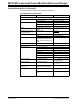
MCP3901 LOW-COST POWER MONITOR REFERENCE DESIGN Appendix B. Bill of Materials TABLE B-1: Qty BILL OF MATERIALS Reference Description Manufacturer Part Number 14 C1, C2, C8, C10, CAP .10UF 50V CERAMIC X7R Yageo Corporation C11, C13, C14, 0805 C16, C17, C18, C19, C20, C28, C30 CC0805KRX7R9BB104 3 C3, C4, C5 CAP TANT LOESR 220UF 6.3V AVX Corporation 10%SMD CASE C TPSC227K006R0125 1 C6 CAP FLM 2.
MCP3901 Low-Cost Power Monitor Reference Design TABLE B-1: Qty BILL OF MATERIALS (CONTINUED) Reference Description Manufacturer 1 R24 RES 510 OHM 1/10W 5% 0603 SMD 1 R25 RES 4.7K OHM 1/10W 5% 0603 Yageo Corporation SMD RC0603JR-074K7L 2 R32, R42 RES 22 OHM 1/10W 1% 0606 SMD Yageo Corporation RC0603FR-0722RL 1 R35, R43 RES 0.
Bill of Materials NOTES: 2010 Microchip Technology Inc.
Worldwide Sales and Service AMERICAS ASIA/PACIFIC ASIA/PACIFIC EUROPE Corporate Office 2355 West Chandler Blvd. Chandler, AZ 85224-6199 Tel: 480-792-7200 Fax: 480-792-7277 Technical Support: http://support.microchip.com Web Address: www.microchip.