
User manual


MCP355X Sensor Application Developer’s Board User’s Guide
DS51609A-page 16 © 2006 Microchip Technology Inc.
3.2.2.5 FULL-SCALE VALUE SELECTION
This menu options loads the DISPLAY_FS_VAL register. This is to allow for proper LCD
display during system design. For example, if a system is being designed that uses
“100 grams” as the full-scale calibration weight, this menu is used to set the value “100”
into the DISPLAY_FS_VAL register. The full-scale value options are 1, 2, 5, 10, 20, 50,
100, 200, or 500.
3.2.2.6 FULL-SCALE CALIBRATION
When in this menu, the second button becomes the calibrate full-scale button, labeled
OK. When this button is selected, the most recent ADC value, after averaging, will be
loaded into the FS
CAL
register.
3.3 PIC18F4550
This device acts as I
2
C slave and passes the PIC16F877 output data from either
channel 1 or channel 2 to the DataView on the PC. All averaging and channel 1
switching that is performed by the PIC16F877 occurs before the data is passed to the
PIC18F4550 and PC.
Note: If the channel mode “Channel 1 Switching” is selected, the averaging will
actually be twice due to the positive and reverse polarity switched samples
being collected.
Note: When displaying the value on the LCD display, the decimal point does not
move. This is to relax the LCD activity and keep the decimal point (and all
digits) from constantly switching location when the LCD output is
calculated.
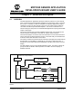
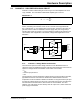
Note: The PIC18F4550 passes data to DataView on the PC coming from the
PIC16F877. This allows a system developer to write PIC16F877 firmware
that averages or otherwise post processes ADC data and then use the PC
to view this post processed data, see section below. Refer to Figure 2-1 for
Data Flow.