
User manual


MCP355X Sensor Application Developer’s Board User’s Guide
DS51609A-page 14 © 2006 Microchip Technology Inc.
3.2.2 Controlling the LCD Menu
The right most button F3 is the menu control button.
.
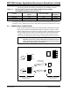
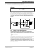
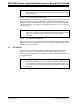
FIGURE 3-1: LCD showing the Averaging Menu. Also shown are the F1, F2
and F3 buttons.
Pressing this button will cycle through the menu options and change the functionality
of the other two buttons, F1 and F2. The LCD text above the buttons describes the
functionality for the different menus.
Here are the LCD menus that can be selected using the F3 button:
• Zero Calibrate - Enable/Disable/Hold
• Channel Select
•Units
• Averaging
• Full-Scale Value Selection
• Full-Scale Calibration
There are four different menu options that will be described in individual sections.
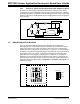
3.2.2.1 ZERO CALIBRATE
When in this menu, the first button becomes the ZERO button. When this button is
selected, the most recent ADC value after averaging will be loaded into the ZERO
CAL
register.
Zero calibration is also enabled or disabled by pressing the ZERO button. This is
indicated by a change of the spinning character on the far top-right of the display, (i.e.:
a LINE is inserted under the spinning character when zero calibration is turned ON.)
When enabled, ZERO
CAL
is subtracted as per Equation 3-1. Refer to Figure 3-2.
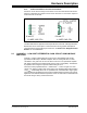
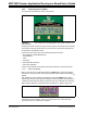
FIGURE 3-2: These two icons show the presence of the zero offset
substraction in the calculation. The icon on the right has a bar underneath that
represents when zero subtraction is enabled.