
User manual


MCP355X SENSOR APPLICATION
DEVELOPER’S BOARD USER’S GUIDE
© 2006 Microchip Technology Inc. DS51609A-page 13
Chapter 3. Firmware Description
3.1 FIRMWARE OVERVIEW
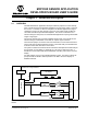
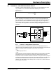
The MCP355X Sensor Application Developer’s Board contains two PICmicro MCUs,
the PIC18F4550, which is solely used to send ADC data to DataView on the PC and
the PIC16F877 which interfaces to the LCD display. Both controllers come pro-
grammed with dedicated firmware that is described in this chapter.
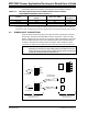
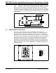
3.2 PIC16F877
This device comes programmed with LCD firmware to ease weigh scale or other
system design. The three push buttons F1, F2, and F3 control both the MCP3551
sampling and LCD output through the PIC16F877.
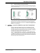
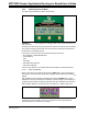
3.2.1 LCD Numerical Output Display
This display will change depending on the units selected and the values that are loaded
into the zero calibrate, full-scale calibrate, and full-scale value registers. To show raw
ADC output, the unit menu is used to select A/D units. When grams (g), or kilograms
(kg) is selected, Equation 3-1 represents the algorithm and formula applied to yield an
output on the LCD display.
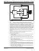
EQUATION 3-1:
Output
ADC
VAL
ZERO
CAL
–
FS
CAL
----------------------------------------------------
⎝⎠
⎛⎞
DISPLAY_FS_VAL
×
=
Where:
ADC
VAL
= The most recent value from the ADC after averaging.
ZERO
CAL
= The most recent ADC
VAL
when the calibrate zero switch
is pressed.
FS
CAL
= The most recent (ADC
VAL
- ZERO
CAL
) when the
calibrate full-scale switch is pressed.
DISPLAY_FS_VAL = 1, 2, 5, 10, 20, 50, 100, 200, or 500 (value selected
using push button switches.)
See Section 3.2.2.5 “Full-Scale Value Selection”
Note: The ZERO
CAL
subtraction to remove zero offset can be enabled or
disabled. See Section 3.2.2.1 “Zero calibrate” for complete
description