
User manual


MCP355X Sensor Application Developer’s Board User’s Guide
DS51609A-page 12 © 2006 Microchip Technology Inc.
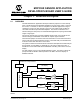
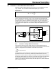
2.4.2 Channel 2 - Direct-Connect Applications (No Amplifier or Gain)
Channel 2 can also be used to evaluate the MCP355X in a direct-connect sensor
configuration. This is accomplished using the 14-pin dual row header JP2. Changing
the headers to DIRECT+ and DIRECT- will take the signal present on the channel input
header (P7) directly into the MCP355X. Figure 2-6 represents this circuit configuration
using channel 2.
FIGURE 2-6: A Direct-connect Weigh Scale.
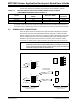
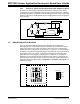
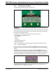
2.5 BRIDGE SIMULATOR BOARDS
There are two small boards included with the MCP355X Sensor Application
Developer’s Board. These boards represent a simulation of an external wheatstone
bridge that is either at zero-scale or full-scale. These boards come populated with
resistors that have a temperature drift specification of 10 ppm/C. For the best bridge
simulation, it is recommended that the bridges be populated with very low drift resistors
with a tempco value of 0.1 ppm/C. Typical load cell bridges will exhibit this output
temperature drift. These boards can be plugged in to either P6 or P7 to assist in
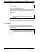
eliminating any error associated with an external sensor. Figure 2-7 represents the
bridge simulator boards and how they should be connected to the MCP355X Sensor
Application Developer’s Board. Refer to Appendix A. “Schematic and Layouts” for
complete schematic.
FIGURE 2-7: Bridge Simulator Boards.
C
1
R
1
V
IN
-
V
IN
+
V
SS
V
DD
V
REF
MCP3551
-SENSE
-IN
-OUT
+OUT
+IN
+SENSE
P6 (OR P7)
Bridge Simulator Boards