
User manual


Hardware Description
© 2006 Microchip Technology Inc. DS51609A-page 9
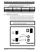
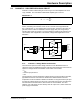
2.2.1 6-Wire and 4-Wire Load Cell Connections
P6 and P7 can be used to easily connect either 4 or 6-wire external load cell sensors.
Figure 2-3 describes how jumpers can be used to short the “In” and “Sense” inputs for
4-wire load cell connections.
FIGURE 2-3: 6-Wire and 4-Wire Load Cell connections on P6 and P7.
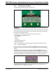
The MCP355X Sensor Application Developer’s Board comes with 2 “Bridge Simulator”
Boards that can be used in place of external sensors during system development.
These boards are plugged directly into P6 and P7, see Section 2.5 “Bridge Simulator
Boards” for more information.
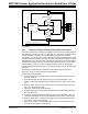
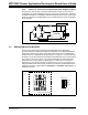
2.3 CHANNEL 1 - LOW-COST DIFFERENTIAL GAIN CIRCUIT USING MCP6XX
AMPLIFIER
Channel 1 contains a differential gain circuit using a dual amplifier PDIP socket
populated with Microchip’s MCP617 amplifier with two analog switches for offset
cancellation. The goal of the circuit is to allow for the use of an operational amplifier
with higher offset drift (which will generally mean a lower cost amplifier). The MCP617
is populated and configured to provide a differential gain of 21.
The board comes populated with R
G
=100Ω and R
F
= 1.0 kΩ. The gain of 21 was
chosen such that the voltage noise at the output of the amplifier will be approximately
10 µV
RMS
, substantially above the 2.5 µV RMS noise of the MCP3551. Higher gains
using the MCP617 amplifier will not provide any additional improvement to the system.
Application note AN1030 details the operation of this circuit and also includes data and
test results using a variety of external sensors.