
User manual


MCP355X Sensor Application Developer’s Board User’s Guide
DS51609A-page 8 © 2006 Microchip Technology Inc.
The following table shows example noise results of the two different channels.
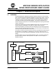
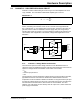
2.2 SENSOR INPUT CONNECTIONS
There are three connectors located on the right hand side of the board for external
sensor input. The first is a standard DB9 connector that goes to a dual row 10-pin
header. Jumper wires must be used to connect the output of the header to the 12-pin
dual row headers going into either of the differential gain circuits described below.
In addition, there are two 3-terminal screw connectors, AUX1 and AUX2. These
connectors go directly into the right hand side of the 40-pin dual row connector P8.
FIGURE 2-2: Sensor Input Connections.
TABLE 2-1: MCP355X SENSOR APPLICATION DEVELOPER’S BOARD CHANNEL
PERFORMANCE EXAMPLE RESULTS (NOTE 1)
Channel
Effective Number of Bits
(ENOB)
“Noise-free” ENOB
“Noise-free
Resolution”
Channel 1 15.8 13.1 8,800:1
Channel 2 18.8 16.1 70,000:1
Direct Connection (No Gain) 13 10.4 1,350:1
Note 1: Higher resolution systems are possible with averaging and other design approaches, table only serves as
an example. Sensor used for these results was a 200 kg external load cell. Amplifier used in Channel 1
was MCP617 device. Amplifier used in Channel 2 was CS3002. All results using MCP3551 A/D Converter.
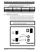
Note: Connector P6 is the input for channel 1, and P7 is the input for channel 2.
Depending on which sensor inputs (AUX1, AUX2, or the DB9 connector) are
used to connect the external sensor to either channel, jumper wires must be
connected to bring the input into either P6 or P7.
-SENSE
-IN
-OUT
+OUT
+IN
+SENSE
5
9
4
8
3
7
2
6
1
J4
P6
TO CHANNEL 1
-SENSE
-IN
-OUT
+OUT
+IN
+SENSE
P7
TO CHANNEL 2
P3
P9
P10
Analog Input Headers To Signal
Conditioning Circuits
Headers Supplied For External
Sensor Connection
JUMPER WIRES
(NOT INCLUDED)