
User manual


MCP355X SENSOR APPLICATION
DEVELOPER’S BOARD USER’S GUIDE
© 2006 Microchip Technology Inc. DS51609A-page 7
Chapter 2. Hardware Description
2.1 OVERVIEW
The MCP355X Sensor Application Developer’s Board’s purpose is to ease develop-
ment of small signal sensor MCP355X applications such as weigh scales. There are
two circuits, or channels, to allow for comparison of different approaches to signal
conditioning circuits. The first channel is a low-cost, low-power signal conditioning
circuit that uses Microchip’s MCP6XX amplifiers. This circuit is intended to be a
reference design for low power, low cost MCP355X applications requiring intermediate
ranges of signal gain.
The second channel uses a precision amplifier with high gain. It is intended to be a
reference design for MCP355X circuits that can require higher resolution.
The board has jumper connections and screw terminals to connect external sensors
such as load cells or RTD temperature sensors. The board easily accomodates both
4-wire and 6-wire load cells sensor connections.
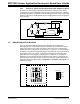
The system includes two PICmicro MCUs for firmware development and data analysis
through either an LCD display or graphically on a PC using a USB connection. A
PIC16F877 communicates with the two MCP355X channels, push-buttons and LCD
display.
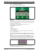
For data analysis on the PC the USB PIC18F4550 is used. This device collects the
post processed PIC16F877 data and passes it via USB to the PC for display on
DataView software.
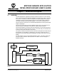
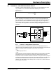
FIGURE 2-1: MCP355X Sensor Application Developer’s Board Functional Block Diagram and
Results.
Push Button Control Switches
PIC18F4550
PIC16F877
SPI
LCD Display
I
2
C
GAIN
CHANNEL 1
USB to PC running DataView
MCP3551 ΔΣ
ADC
GAIN
CHANNEL 2
Sensor Input Connections
8
3
4
MCP3551 ΔΣ
ADC