MCP355X Sensor Application Developer’s Board User’s Guide © 2006 Microchip Technology Inc.
Note the following details of the code protection feature on Microchip devices: • Microchip products meet the specification contained in their particular Microchip Data Sheet. • Microchip believes that its family of products is one of the most secure families of its kind on the market today, when used in the intended manner and under normal conditions. • There are dishonest and possibly illegal methods used to breach the code protection feature.
MCP355X SENSOR APPLICATION DEVELOPER’S BOARD USER’S GUIDE Table of Contents Preface ........................................................................................................................... 1 Introduction............................................................................................................ 1 Document Layout .................................................................................................. 1 Conventions Used in this Guide ...............................
MCP355X Sensor Application Developer’s Board User’s Guide Appendix A. Schematic and Layouts ........................................................................21 A.1 Introduction .................................................................................................. 21 A.2 Schematic - Page 1 .................................................................................... 22 A.3 Schematic - Page 2 .................................................................................... 23 A.
MCP355X SENSOR APPLICATION DEVELOPER’S BOARD USER’S GUIDE Preface NOTICE TO CUSTOMERS All documentation becomes dated, and this manual is no exception. Microchip tools and documentation are constantly evolving to meet customer needs, so some actual dialogs and/or tool descriptions may differ from those in this document. Please refer to our web site (www.microchip.com) to obtain the latest documentation available. Documents are identified with a “DS” number.
MCP355X Sensor Application Developer’s Board User’s Guide CONVENTIONS USED IN THIS GUIDE This manual uses the following documentation conventions: DOCUMENTATION CONVENTIONS Description Arial font: Italic characters Represents Examples Referenced books Emphasized text A window A dialog A menu selection A field name in a window or dialog A menu path MPLAB® IDE User’s Guide ...is the only compiler...
Preface THE MICROCHIP WEB SITE Microchip provides online support via our web site at www.microchip.com. This web site is used as a means to make files and information easily available to customers.
MCP355X Sensor Application Developer’s Board User’s Guide NOTES: DS51609A-page 4 © 2006 Microchip Technology Inc.
MCP355X SENSOR APPLICATION DEVELOPER’S BOARD USER’S GUIDE Chapter 1. Product Overview 1.1 INTRODUCTION This chapter provides an overview of the MCP355X Sensor Application Developer’s Board and covers the following topics: • What is the MCP355X Sensor Application Developer’s Board? • What the MCP355X Sensor Application Developer’s Board Kit includes 1.
MCP355X Sensor Application Developer’s Board User’s Guide 1.
MCP355X SENSOR APPLICATION DEVELOPER’S BOARD USER’S GUIDE Chapter 2. Hardware Description 2.1 OVERVIEW The MCP355X Sensor Application Developer’s Board’s purpose is to ease development of small signal sensor MCP355X applications such as weigh scales. There are two circuits, or channels, to allow for comparison of different approaches to signal conditioning circuits. The first channel is a low-cost, low-power signal conditioning circuit that uses Microchip’s MCP6XX amplifiers.
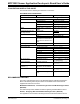
MCP355X Sensor Application Developer’s Board User’s Guide The following table shows example noise results of the two different channels. TABLE 2-1: MCP355X SENSOR APPLICATION DEVELOPER’S BOARD CHANNEL PERFORMANCE EXAMPLE RESULTS (NOTE 1) Effective Number of Bits (ENOB) Channel “Noise-free” ENOB “Noise-free Resolution” Channel 1 15.8 13.1 8,800:1 Channel 2 18.8 16.1 70,000:1 Direct Connection (No Gain) 13 10.
Hardware Description 2.2.1 6-Wire and 4-Wire Load Cell Connections P6 and P7 can be used to easily connect either 4 or 6-wire external load cell sensors. Figure 2-3 describes how jumpers can be used to short the “In” and “Sense” inputs for 4-wire load cell connections. FIGURE 2-3: 6-Wire and 4-Wire Load Cell connections on P6 and P7. The MCP355X Sensor Application Developer’s Board comes with 2 “Bridge Simulator” Boards that can be used in place of external sensors during system development.
MCP355X Sensor Application Developer’s Board User’s Guide U7 Analog Switch MCP6XX Socket U9 + VREF SPI VINRF MCP3551 VSS P6 RG VIN+ U5 -SENSE -IN -OUT +OUT +IN +SENSE + Analog Switch U8 Switch Control From PIC16F877 FIGURE 2-4: cancellation. 2.3.
Hardware Description 2.4 CHANNEL 2 - HIGH-PRECISION GAIN CIRCUIT Channel 2 contains a differential gain circuit using a low noise amplifier from Cirrus Logic, CS3002. The noise allows a differential amplifier gain of 103 V/V. EQUATION 2-1: RF G = 1 + 2 〈 -------〉 RG This was chosen so that the amplifier noise would be similar to that of the MCP3551 device, maximizing the resolution of the circuit. The board comes populated with RG = 100Ω and RF = 5.1 kΩ.
MCP355X Sensor Application Developer’s Board User’s Guide 2.4.2 Channel 2 - Direct-Connect Applications (No Amplifier or Gain) Channel 2 can also be used to evaluate the MCP355X in a direct-connect sensor configuration. This is accomplished using the 14-pin dual row header JP2. Changing the headers to DIRECT+ and DIRECT- will take the signal present on the channel input header (P7) directly into the MCP355X. Figure 2-6 represents this circuit configuration using channel 2. R1 VIN+ VIN- FIGURE 2-6: 2.
MCP355X SENSOR APPLICATION DEVELOPER’S BOARD USER’S GUIDE Chapter 3. Firmware Description 3.1 FIRMWARE OVERVIEW The MCP355X Sensor Application Developer’s Board contains two PICmicro MCUs, the PIC18F4550, which is solely used to send ADC data to DataView on the PC and the PIC16F877 which interfaces to the LCD display. Both controllers come programmed with dedicated firmware that is described in this chapter. 3.
MCP355X Sensor Application Developer’s Board User’s Guide 3.2.2 Controlling the LCD Menu The right most button F3 is the menu control button. . FIGURE 3-1: and F3 buttons. LCD showing the Averaging Menu. Also shown are the F1, F2 Pressing this button will cycle through the menu options and change the functionality of the other two buttons, F1 and F2. The LCD text above the buttons describes the functionality for the different menus.
Firmware Description In disabled mode, ZEROCAL is not subtracted per Equation 3-1. When displaying the direct ADC value (units = ADU), the output is simply the decimal representation of ADCVAL. If zero calibrate is enabled, then ZEROCAL is subtracted before the value is displayed. Pressing the HOLD button freezes the LCD display to allow for viewing in fast sampling modes (less averaging). Pressing the HOLD button again will resume normal operation. 3.2.2.
MCP355X Sensor Application Developer’s Board User’s Guide Note: 3.2.2.5 If the channel mode “Channel 1 Switching” is selected, the averaging will actually be twice due to the positive and reverse polarity switched samples being collected. FULL-SCALE VALUE SELECTION This menu options loads the DISPLAY_FS_VAL register. This is to allow for proper LCD display during system design.
MCP355X SENSOR APPLICATION DEVELOPER’S BOARD USER’S GUIDE Chapter 4. DataView 4.1 OVERVIEW DataView is a graphical data analysis tool that interfaces to many of Microchip’s stand-alone A/D converter demonstration or evaluation boards via USB interface. Each installation of Dataview is specific to the A/D converter and will contain one or more of the following graphical output windows: • Scope Plot • Histogram • Auxiliary Data Note: 4.
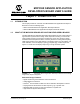
MCP355X Sensor Application Developer’s Board User’s Guide 4.3 NOISE HISTOGRAM WINDOW The noise histogram window displays the ADC output in histogram form, building the number of occurrences in each bin with each consecutive sample. The difference between each bin from the mean in units of LSB is given as the y-axis. The sample size can be changed in the configuration window. FIGURE 4-2: 4.4 Noise Histogram Window.
DataView 4.5 CONFIGURING DATAVIEW The sample size and polling interval of the USB interface can be changed to accommodate customized firmware on the PICmicro microcontroller side. The units of millisecond, seconds, minute, hour or day can be used to change the functionality of the system. This allows the device to be used as a “Data Logger”. Note that if the polling interval is shorter than the sampling rate on the hardware size, duplicate data will be included in the sample set.
MCP355X Sensor Application Developer’s Board User’s Guide NOTES: DS51609A-page 20 © 2006 Microchip Technology Inc.
MCP355X SENSOR APPLICATION DEVELOPER’S BOARD USER’S GUIDE Appendix A. Schematic and Layouts A.1 INTRODUCTION This appendix contains the following schematics and layouts for the MCP355X Sensor Application Developer’s Board: • • • • • • • Board Schematic, Pages 1 thru 3 Board Schematic - Bridge Simulator Board - Top Layer and Silk Screen Board - Top Layer Board - Bottom Layer and Silk Screen Board - Bottom Layer Board - Bridge Simulator Layout © 2006 Microchip Technology Inc.
MCP355X Sensor Application Developer’s Board User’s Guide SCHEMATIC - PAGE 1 M A.2 DS51609A-page 22 © 2006 Microchip Technology Inc.
Schematic and Layouts SCHEMATIC - PAGE 2 M A.3 © 2006 Microchip Technology Inc.
MCP355X Sensor Application Developer’s Board User’s Guide SCHEMATIC - PAGE 3 M A.4 DS51609A-page 24 © 2006 Microchip Technology Inc.
Schematic and Layouts SCHEMATIC - BRIDGE SIMULATOR M A.5 © 2006 Microchip Technology Inc.
MCP355X Sensor Application Developer’s Board User’s Guide A.6 BOARD LAYOUT - TOP LAYER AND SILK SCREEN MCP355x SENSOR APPLICATION DEVELOPER'S BOARD A.7 BOARD LAYOUT - TOP LAYER DS51609A-page 26 © 2006 Microchip Technology Inc.
Schematic and Layouts A.8 BOARD LAYOUT - BOTTOM LAYER AND SILK SCREEN A.9 BOARD LAYOUT - BOTTOM LAYER © 2006 Microchip Technology Inc.
MCP355X Sensor Application Developer’s Board User’s Guide A.10 BOARD LAYOUT - BRIDGE SIMULATOR DS51609A-page 28 © 2006 Microchip Technology Inc.
MCP355X SENSOR APPLICATION DEVELOPER’S BOARD USER’S GUIDE Appendix B. Bill Of Materials (BOM) TABLE B-1: Qty BILL OF MATERIALS (BOM) Designator Description 17 C1, C3, C4, C5, CAP .1UF 25V CERAMIC X7R C6, C11, C12, 0805 C14, C15, C16, C17, C18, C29, C33, C34, C37, C39 11 C2, C9, C10, C19, C20, C21, C22, C27, C30, C35, C36 4 Manufacturer ® Part Number Panasonic - ECG ECJ-2VB1E104K CAP CER 10UF 6.
MCP355X Sensor Application Developer’s Board User’s Guide TABLE B-1: Qty BILL OF MATERIALS (BOM) (CONTINUED) Designator Description Manufacturer Part Number 2 P2, P4 6 X 1 Header 2.54mm on center 6 mm/2.5mm Samtec TSW-106-07-G-S 1 P3 5 X 2 Header 2.54mm on center 6 mm/2.5mm Samtec TSW-105-07-G-D 2 P5, P8 20 X 2 Header 2.54mm on center 6 Samtec mm/2.5mm TSW-120-07-G-D 2 P6, P7 6 X 2 Header 2.54mm on center 6 mm/2.5mm Samtec TSW-106-07-G-D 2 P9, P10 3.
Bill Of Materials (BOM) TABLE B-1: Qty BILL OF MATERIALS (BOM) (CONTINUED) Designator Description Manufacturer 1 U3 40-Pin Enhanced Flash Microcontrollers 1 U4 256K I2C™ CMOS Serial EEPROM Microchip Technology Inc. 24FC256-I/SN 2 U5, U6 22-Bit Delta Sigma ADC SO-8 Microchip Technology Inc. MCP3551-E/SN 2 U7, U8 IC SWITCH ANALOG SPDT LV SC70-6 Fairchild Semiconductor® FSA4157P6X_NL 1 U9 Dual Op-Amp DIP-8 (Install in socket)) Microchip Technology Inc.
WORLDWIDE SALES AND SERVICE AMERICAS ASIA/PACIFIC ASIA/PACIFIC EUROPE Corporate Office 2355 West Chandler Blvd. Chandler, AZ 85224-6199 Tel: 480-792-7200 Fax: 480-792-7277 Technical Support: http://support.microchip.com Web Address: www.microchip.