
User manual

MCP355X TINY APPLICATION
SENSOR DEMO BOARD USER’S
© 2006 Microchip Technology Inc. DS51598A-page 11
Appendix A. Schematic and Layouts
A.1 INTRODUCTION
This appendix contains the following schematics and layouts for the MCP355X Tiny
Application Sensor Demo Board User’s Guide:
• Board Schematic
• Board - Top Layer
• Board - Bottom Layer
A.2 SCHEMATICS AND PCB LAYOUT
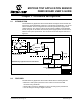
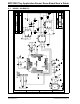
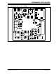
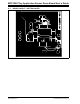
Figure A.3 “Board - Schematic” shows the MCP355X Tiny Application Sensor Demo
Board schematic, while Figure A.4 “Board Layout - Top Layer” and Figure
A.5 “Board Layout - Bottom Layer” show the layout for the two different layers. The
layer order is shown in Figure A-1.
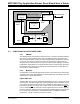
FIGURE A-1: LAYER ORDER
Top Layer
Bottom Layer