MCP3425 SOT23-6 Evaluation Board User’s Guide © 2009 Microchip Technology Inc.
Note the following details of the code protection feature on Microchip devices: • Microchip products meet the specification contained in their particular Microchip Data Sheet. • Microchip believes that its family of products is one of the most secure families of its kind on the market today, when used in the intended manner and under normal conditions. • There are dishonest and possibly illegal methods used to breach the code protection feature.
MCP3425 SOT23-6 EVALUATION BOARD USER’S GUIDE Table of Contents Preface ........................................................................................................................... 1 Introduction............................................................................................................ 1 Document Layout .................................................................................................. 1 Conventions Used in this Guide ...........................................
MCP3425 SOT23-6 Evaluation Board User’s Guide NOTES: DS51787A-page iv © 2009 Microchip Technology Inc.
MCP3425 SOT23-6 EVALUATION BOARD USER’S GUIDE Preface NOTICE TO CUSTOMERS All documentation becomes dated, and this manual is no exception. Microchip tools and documentation are constantly evolving to meet customer needs, so some actual dialogs and/or tool descriptions may differ from those in this document. Please refer to our web site (www.microchip.com) to obtain the latest documentation available. Documents are identified with a “DS” number.
MCP3425 SOT23-6 Evaluation Board User’s Guide CONVENTIONS USED IN THIS GUIDE This manual uses the following documentation conventions: DOCUMENTATION CONVENTIONS Description Arial font: Italic characters Represents Referenced books Emphasized text A window A dialog A menu selection A field name in a window or dialog A menu path MPLAB® IDE User’s Guide ...is the only compiler...
Preface RECOMMENDED READING This user's guide describes how to use the MCP3425 SOT23-6 Evaluation Board with the PICkit Serial Analyzer. The following Microchip documents are available and recommended as supplemental reference resources. PICkit™ Serial Analyzer User’s Guide, DS51647 Consult this document for instructions on how to use the PICkit Serial Analyzer hardware and software.
MCP3425 SOT23-6 Evaluation Board User’s Guide DOCUMENT REVISION HISTORY Revision A (January 2009) • Initial Release of this Document. DS51787A-page 4 © 2009 Microchip Technology Inc.
MCP3425 SOT23-6 EVALUATION BOARD USER’S GUIDE Chapter 1. Quick Start Instructions 1.1 INTRODUCTION The following sections provide an overview of the MCP3425 SOT23-6 Evaluation Board and demonstrate how to use it with the PICkit™ Serial Analyzer (P/N: DV164122). The following topics are covered: • Description of the MCP3425 SOT23-6 Evaluation Board • Using MCP3425 SOT23-6 Evaluation Board with the PICkit Serial Analyzer to evaluate the MCP3425 device. 1.
MCP3425 SOT23-6 Evaluation Board User’s Guide 1.2.1 I2C Address Bits The I2C device code and address bits of the MCP3425 device in this evaluation board are pre-programmed at factory (Code: 1101000). FIGURE 1-1: Board. DS51787A-page 6 Front and Back Views of the MCP3425 SOT23-6 Evaluation © 2009 Microchip Technology Inc.
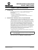
Quick Start Instructions 1.3 GETTING STARTED WITH PICKIT™ SERIAL ANALYZER Figure 1-1 shows the MCP3425 SOT23-6 Evaluation Board, while Figure 1-2 shows the evaluation board and the PICkit Serial Analyzer connection. The following instructions show how to use them together: 1. Connect the MCP3425 SOT23-6 Evaluation Board’s J1 pin socket to the PICkit Serial Analyzer, as shown in Figure 1-2. 2. Connect oscilloscope probes to SCL and SDA test pins (optional). 3.
MCP3425 SOT23-6 Evaluation Board User’s Guide Personal Computer USB Cable Connected between the PICkit Serial analyzer and Personal Computer PICkit Serial Analyzer Sensor Input Connectors MCP3425 Evaluation Board FIGURE 1-2: MCP3425 SOT23-6 Evaluation Board with the PICkit™ Serial Analyzer. 1.3.
Quick Start Instructions FIGURE 1-3: PICkit Serial Analyzer Configuration Wizard Welcome Window. 4. Select the Communication Mode type: I2C Master, and click the Next button. FIGURE 1-4: © 2009 Microchip Technology Inc. Step 1 - Communication Mode Selection.
MCP3425 SOT23-6 Evaluation Board User’s Guide 5. Select 100 kHz or 400 kHz. Either one will be fine. Click the Next button. FIGURE 1-5: Note: Step 2 - I2C Communication Speed Window. The MCP3425 device supports the I2C bus data rate up to 3.4 MHz, but the current version of the PICkit Serial Analyzer supports the I2C bus data rate up to 400 kHz only. 6. Select No on Enable Pull-ups and click the Next button. Note: The MCP3425 SOT23-6 Evaluation Board has its own pull-up resistors.
Quick Start Instructions 7. Select the VDD voltage of the MCP3425 SOT23-6 Evaluation Board and click the Next button. Case 1: When you use VDD from the PICkit Serial Analyzer: If you choose PICkit Serial will power my device and 5 Volt as shown below, the MCP3425 SOT23-6 Evaluation Board is powered by the 5V DC from the PICkit Serial Analyzer through the JP1 jumper. In this case, make sure that the JP1 jumper on the MCP3425 SOT23-6 Evaluation Board is connected.
MCP3425 SOT23-6 Evaluation Board User’s Guide 8. Click the OK button. You have made all of the PICkit Serial Analyzer Configuration Set-ups. You are now ready to program the MCP3425 SOT23-6 Evaluation Board using the PICkit Serial Analyzer. FIGURE 1-8: DS51787A-page 12 Configuration Wizard - Finishing Step. © 2009 Microchip Technology Inc.
Quick Start Instructions 1.3.2 Creating Script Files In order to make a communication between the PICkit Serial Analyzer and the MCP3425 SOT23-6 Evaluation Board, a script file is needed. The following procedure shows how to create script files and how to use them. • Select Communication -> Script -> Script Builder. FIGURE 1-9: © 2009 Microchip Technology Inc. Creating a Script File with Script Builder.
MCP3425 SOT23-6 Evaluation Board User’s Guide 1.3.2.1 CREATING A SCRIPT FILE FOR CONFIGURATION BYTE WRITING 1. Click on WriteBlockAddrA8 in “Example I2C Scripts” column. • This will result in filling in the spaces under Script Detail column. Now you can modify the Script Detail column parameters by clicking with the right mouse button. Modifying the Script Details parameters: 1. Under the Script Detail box, select the item in the parameter box. 2.
Quick Start Instructions 5. Change the parameter value. Script Detail I2CSTART I2CWRTBYT 02 D0 98 I2CSTOP Note: © 2009 Microchip Technology Inc. * * ------> This means there are two bytes to send ------> 1st Write Byte: Address byte with W/R bit = 1101-0000 ------> 2nd Write Byte: Configuration byte = 1001-1000 * All 6 parameters above must be listed in the same order as shown here. The parameters above with * are not modifiable. Address bits (A2, A1, A0) = (0,0,0) for this evaluation board.
MCP3425 SOT23-6 Evaluation Board User’s Guide 2 Bytes to send Address Byte Configuration Byte (98) Note the 98 in the configuration byte selects the following options: - Conversion Mode: Continuous Conversion - Bit Resolution: 16 bits - Gain Selection: 1x FIGURE 1-11: DS51787A-page 16 Script File Example for the I2C Write Command. © 2009 Microchip Technology Inc.
Quick Start Instructions 1.3.2.2 SAVING THE SCRIPT FILE AND PROGRAMMING THE CONFIGURATION REGISTER 1. Change the 2nd and 3rd data bytes you want in the Script Detail. 2. Type in any script name (i.e., MCP3425_Wr_16Bit) in the space below the Script Name menu. 3. Click Save Script button. 4. Click Execute Script button. Note: At this point, the PICkit Serial transmits the I2C Write command to the MCP3425 device.
MCP3425 SOT23-6 Evaluation Board User’s Guide 1.3.3 Reading the Conversion Data using the PICkit Serial Analyzer You can read back the conversion data with the following steps. 1.3.3.1 CREATING A SCRIPT FILE TO READ CONVERSION DATA 1. Click on ReadAddrA8 in “Example I2C Scripts” column. • This will result in filling in the spaces under the Script Detail column. Now you can modify the parameter boxes (delete or insert) in the Script Detail column with options.
Quick Start Instructions Address Byte Requesting 4 Bytes FIGURE 1-13: Script File Sample to Read Conversion Data. 2. Type in any script name (i.e., MCP3425_Read) in the space below the Script Name menu. 3. Click Save Script button. 4. Click Execute Script button. Note: At this point, the PICkit Serial transmits the I2C Read Command to the MCP3425 device. The saved file name will appear in Users I2C Scripts column, and can be re-used any time by selecting the file name. 5.
MCP3425 SOT23-6 Evaluation Board User’s Guide Requesting Requesting 4 Bytes 4 Bytes Reading Conversion Data 4th Byte: Repeated Byte for Configuration byte (note that RDY bit returned to “1” after 4th byte) 3rd byte: Configuration Byte (note that RDYbit is “0”) 2nd byte: Data Byte 1st byte: Data Byte Results: Output code: 1F50 in hex ( = 8016 in decimal) Output Voltage: 8016 x 62.5 µV (LSB) = 0.501V Note: * 1 LSB for 16 bit = 62.6 µV * Input at CH1 = 0.
Quick Start Instructions Zoom-in Data Bytes = 0101AD (hex) (a) Read command and outputs. The 3 data bytes are zoomed in for better clarity. Zoom-in 3rd Byte 4th Byte RDY bit RDY bit Configuration Byte and Repeated Configuration Byte (b) Read command and outputs. The last two data bytes are zoomed in for better clarity. FIGURE 1-15: Read Command and Data on I2C bus. Note the RDY bit in 3rd byte is “0”. This means the conversion data just read is the latest conversion data.
MCP3425 SOT23-6 Evaluation Board User’s Guide NOTES: DS51787A-page 22 © 2009 Microchip Technology Inc.
MCP3425 SOT23-6 EVALUATION BOARD USER’S GUIDE Appendix A. Schematic and Layouts A.1 INTRODUCTION This appendix contains the following schematics and layouts for the MCP3425 SOT23-6 Evaluation Board: • • • • Board – Schematic Board – Top Layer Board – Top Metal Layer Board – Bottom Layer © 2009 Microchip Technology Inc.
MCP3425 SOT23-6 Evaluation Board User’s Guide A.2 BOARD – SCHEMATIC DS51787A-page 24 © 2009 Microchip Technology Inc.
Schematic and Layouts A.3 BOARD – TOP LAYER © 2009 Microchip Technology Inc.
MCP3425 SOT23-6 Evaluation Board User’s Guide A.4 BOARD – TOP METAL LAYER DS51787A-page 26 © 2009 Microchip Technology Inc.
Schematic and Layouts A.5 BOARD – BOTTOM LAYER © 2009 Microchip Technology Inc.
MCP3425 SOT23-6 Evaluation Board User’s Guide NOTES: DS51787A-page 28 © 2009 Microchip Technology Inc.
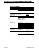
MCP3425 EVALUATION BOARD USER’S GUIDE Appendix B. Bill Of Materials (BOM) TABLE B-1: Qty BILL OF MATERIALS Reference Description Manufacturer Part Number 1 C1 CAP .1UF 25V CERAMIC X7R 0805 Panasonic® - ECG ECJ-2VB1E104K 1 C2 CAP CERAMIC 10UF 6.3V X5R 0805 Panasonic - ECG ECJ-2FB0J106K 1 D1 LED RED ORANGE CLEAR 0805 SMD LITE-ON INC LTST-C170EKT 1 J1 CONN HEADER 6POS .
WORLDWIDE SALES AND SERVICE AMERICAS ASIA/PACIFIC ASIA/PACIFIC EUROPE Corporate Office 2355 West Chandler Blvd. Chandler, AZ 85224-6199 Tel: 480-792-7200 Fax: 480-792-7277 Technical Support: http://support.microchip.com Web Address: www.microchip.