
User manual


MCP3423 EVALUATION BOARD
USER’S GUIDE
© 2008 Microchip Technology Inc. DS51778A-page 5
Chapter 1. Quick Start Instructions
1.1 INTRODUCTION
The following sections provide an overview of the MCP3423 Evaluation Board and
demonstrate how to use it with the PICkit™ Serial Analyzer (P/N: DV164122).
The following topics are covered:
• Description of the MCP3423 Evaluation Board
• How to use MCP3423 Evaluation Board with the PICkit Serial Analyzer
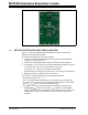
1.2 DESCRIPTION OF THE MCP3423 EVALUATION BOARD
The MCP3423 Evaluation Board (P/N MCP3423EV) contains a MCP3423 18-Bit ΔΣ
Analog-to-Digital Converter (ADC). The MCP3423 is a 2-channel 18 bit delta-sigma
ADC device with various configuration options. The board has analog input connection
pads and various test pads.
The user can connect inputs and test the conversion results using the PICkit Serial
Analyzer and its PC graphic user interface (GUI). The MCP3423 Evaluation Board has
the following interfaces:
• PICkit Serial Analyzer (P/N: DV164122) for writing configuration register bits and
reading the conversion data.
The board has test points for SDL, SDA, and analog inputs. By connecting an
oscilloscope to these test points, the user can examine the data communications
through the I
2
C
™
bus line and observe the resulting conversion output. Refer to
Appendix A. “Schematic and Layouts”.
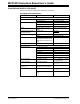
1.2.1 I
2
C Address Bits and A0 Address Bit Selection
The I
2
C device code and address bits of the MCP3423 device are:
• Device Code: ‘1101’
• A2, A1, A0 Address Bits: determined by the JP2 (Adr1 pin) and JP3 (Adr0 pin).
• See Table 1-1 for the I
2
C Device Address bits and JP2 and JP3 connections.
Note: The user can use this board without the PICkit Serial Analyzer as long as
the V
DD
, SCL, and SDA are provided through J1 connector. This Evaluation
Board does not include MCU.