
User manual

Quick Start Instructions
© 2008 Microchip Technology Inc. DS51778A-page 7
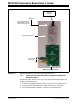
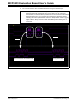
6. Connecting the analog inputs: If you need to measure a single-ended input,
connect the unused pin (example, CHx-) to V
SS
.
• Connecting the inputs: The MCP3423 Evaluation Board has input pads for two
analog input channels. You can connect all inputs at the same time and multiplex
the input channel using configuration register settings. You can also leave the
unused channel inputs floating.
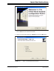
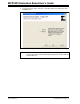
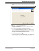
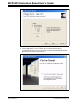
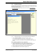
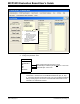
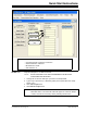
7. Use the PICkit Serial Analyzer PC GUI to send I
2
C write and read commands.
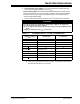
TABLE 1-1: I
2
C ADDRESS BITS VS. JP2 AND JP3 CONNECTORS
CAUTION
Each analog input pin has an ESD diode. Certain input conditions can damage the
device. Please use the following conditions:
(a) Do not apply an input greater than the input range specified by the MCP3423 Data
Sheet.
(b)Apply the input signal after V
DD
is powered-up.
I
2
C Device Address
Bits
JP2 (Adr1 Pin) JP3 (Adr0 Pin)
1101 000 W
/R Connected to V
SS
Connected to V
SS
1101 001 W/R Connected to V
SS
Float
1101 010 W
/R Connected to V
SS
Connected to V
DD
1101 100 W/R Connected to V
DD
Connected to V
SS
1101 101 W/R Connected to V
DD
Float
1101 110 W
/R Connected to V
DD
Connected to V
DD
1101 011 W/R Float Connected to V
SS
1101 111 W/R Float Connected to V
DD
1101 000 W/R Float Float
Note 1: W
/R bit = “0” for writing, “1” for reading.
2: Float: (a) Leave pin without connecting to anything, or (b) apply Addr_Float voltage.
See MCP3423 Data Sheet for more details.