
User manual


MCP3423 Evaluation Board User’s Guide
DS51778A-page 6 © 2008 Microchip Technology Inc.
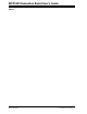
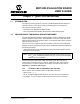
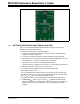
FIGURE 1-1: Front View of the MCP3423 Evaluation Board.
1.3 GETTING STARTED WITH PICKIT SERIAL ANALYZER
Figure 1-1 shows the MCP3423 Evaluation Board, and Figure 1-2 shows the
MCP3423 and PICkit Serial Analyzer.
The following describes how to use them together:
1. Connect the MCP3423 Evaluation Board’s 6-pin socket to the PICkit Serial
Analyzer as shown in Figure 1-2.
2. Connect the oscilloscope probes to the SCL and SDA test pins (optional).
3. V
DD
Selection: You can use the V
DD
from the PICkit Serial Analyzer or use your
own external V
DD
. The JP1 connector selects the V
DD
path.
(a) Connect JP1, if using V
DD
from PICkit Serial Analyzer.
(b) Disconnect JP1 and apply V
DD
at V
DD
1 pin, if you are using an external V
DD
.
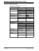
4. Address bit selection using JP2 and JP3 connectors.
The I
2
C device code and address bits of the MCP3423 device are:
• MCP3423 I
2
C device code: ‘1101’
• A2, A1, A0 Address Bits: determined by the JP2 (Adr1 pin) and JP3 (Adr0 pin)
• The JP2 and JP3 connectors are external address bit selections. Connect these
pins to V
SS
, V
DD
, float, or connect any arbitrary voltage
• See Table 1-1 for the I
2
C Device Address bits and JP2 and JP3 connections
5. Connecting V
DD
: LED D1 turns on when V
DD
is applied. The PICkit Serial
Analyzer will provide V
DD
automatically, if it is connected to the PC. Make sure
LED D1 turns on, when you execute the command using the PICkit Serial
Analyzer.