
Datasheet


2013 Microchip Technology Inc. DS22331A-page 167
MCP19111
27.5 I
2
C Master Mode
Master mode is enabled by setting and clearing the
appropriate SSPM bits in the SSPCON1 register and
by setting the SSPEN bit. In Master mode, the SDA and
SCK pins must be configured as inputs. The MSSP
peripheral hardware will override the output driver TRIS
controls when necessary, to drive the pins low.
Master mode of operation is supported by interrupt
generation on the detection of the Start and Stop
conditions. The Stop (P) and Start (S) bits are cleared
from a Reset or when the MSSP module is disabled.
Control of the I
2
C bus may be taken when the P bit is
set, or the bus is Idle.
In Firmware Controlled Master mode, user code
conducts all I
2
C bus operations based on Start and
Stop bit condition detection. Start and Stop condition
detection is the only active circuitry in this mode. All
other communication is done by the user software
directly manipulating the SDA and SCL lines.
The following events will cause the SSP Interrupt Flag
bit, SSPIF, to be set (SSP interrupt, if enabled):
• Start condition detected
• Stop condition detected
• Data transfer byte transmitted/received
• Acknowledge transmitted/received
• Repeated Start generated
27.5.1 I
2
C MASTER MODE OPERATION
The master device generates all of the serial clock
pulses and the Start and Stop conditions. A transfer is
ended with a Stop condition or with a Repeated Start
condition. Since the Repeated Start condition is also
the beginning of the next serial transfer, the I
2
C bus will
not be released.
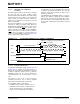
In Master Transmitter mode, serial data is output
through SDA, while SCL outputs the serial clock. The
first byte transmitted contains the slave address of the
receiving device (7 bits) and the Read/Write
(R/W) bit.
In this case, the R/W
bit will be logic ‘0’. Serial data is
transmitted 8 bits at a time. After each byte is transmit-
ted, an Acknowledge bit is received. Start and Stop
conditions are output to indicate the beginning and the
end of a serial transfer.
In Master Receive mode, the first byte transmitted
contains the slave address of the transmitting device
(7 bits) and the R/W
bit. In this case, the R/W bit will be
logic ‘1’. Thus, the first byte transmitted is a 7-bit slave
address followed by a ‘1’ to indicate the receive bit.
Serial data is received via SDA, while SCL outputs the
serial clock. Serial data is received 8 bits at a time. After
each byte is received, an Acknowledge bit is
transmitted. Start and Stop conditions indicate the
beginning and the end of transmission.
A Baud Rate Generator is used to set the clock
frequency output on SCL. See Section 27.6 “Baud
Rate Generator” for more detail.
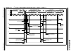
27.5.2 CLOCK ARBITRATION
Clock arbitration occurs when the master, during any
receive, transmit or Repeated Start/Stop condition,
releases the SCL pin (SCL allowed to float high). When
the SCL pin is allowed to float high, the Baud Rate
Generator (BRG) is suspended from counting until the
SCL pin is actually sampled high. When the SCL pin is
sampled high, the Baud Rate Generator is reloaded
with the contents of SSPADD<7:0> and begins
counting. This ensures that the SCL high time will
always be at least one BRG rollover count in the event
that the clock is held low by an external device
(Figure 27-17).
Note 1: The MSSP module, when configured in
I
2
C Master mode, does not allow
queueing of events. For instance, the
user is not allowed to initiate a Start
condition and immediately write the
SSPBUF register to initiate transmission
before the Start condition is complete. In
this case, the SSPBUF will not be written
to and the WCOL bit will be set, indicating
that a write to the SSPBUF did not occur.
2: When in Master mode, Start/Stop
detection is masked and an interrupt is
generated when the SEN/PEN bit is
cleared and the generation is complete.