
Datasheet


MCP19111
DS22331A-page 150 2013 Microchip Technology Inc.
27.3.8 START/STOP CONDITION INTERRUPT
MASKING
The SCIE and PCIE bits of the SSPCON3 register can
enable the generation of an interrupt in Slave modes
that do not typically support this function. These bits
will have no effect on slave modes where interrupt on
Start and Stop detect are already enabled.
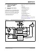
FIGURE 27-4: I
2
C START AND STOP CONDITIONS
FIGURE 27-5: I
2
C RESTART CONDITION
27.3.9 ACKNOWLEDGE SEQUENCE
The 9
th
SCL pulse for any transferred byte in I
2
C is
dedicated as an Acknowledge. It allows receiving
devices to respond back to the transmitter by pulling
the SDA line low. The transmitter must release control
of the line during this time to shift in the response. The
Acknowledge (ACK
) is an active-low signal, pulling the
SDAx line low indicates to the transmitter that the
device has received the transmitted data and is ready
to receive more.
The result of an ACK
is placed in the ACKSTAT bit of
the SSPCON2 register.
Slave software, when the AHEN and DHEN bits are
set, allow the user to set the ACK
value sent back to
the transmitter. The ACKDT bit of the SSPCON2 regis-
ter is set/cleared to determine the response.
Slave hardware will generate an ACK
response if the
AHEN and DHEN bits of the SSPCON3 register are
clear.
There are certain conditions where an ACK
will not be
sent by the slave. If the BF bit of the SSPSTAT register
or the SSPOV bit of the SSPCON1 register are set
when a byte is received, an ACK
will not be sent.
When the module is addressed, after the 8
th
falling
edge of SCL on the bus, the ACKTIM bit of the
SSPCON3 register is set. The ACKTIM bit indicates
the acknowledge time of the active bus. The ACKTIM
Status bit is only active when the AHEN bit or DHEN
bit is enabled.
SDA
SCL
P
Stop
Condition
S
Start
Condition
Change of
Data Allowed
Change of
Data Allowed
Restart
Condition
Sr
Change of
Data Allowed
Change of
Data Allowed