
Datasheet


2013 Microchip Technology Inc. DS22331A-page 147
MCP19111
The I
2
C bus specifies two signal connections:
• Serial Clock (SCL)
• Serial Data (SDA)
Both the SCL and SDA connections are bidirectional
open-drain lines, each requiring pull-up resistors for the
supply voltage. Pulling the line to ground is considered
a logical zero; letting the line float is considered a
logical one.
Before selecting any I
2
C mode, the SCL and SDA pins
must be programmed to inputs by setting the
appropriate TRIS bits. Selecting I
2
C mode, by setting
the SSPEN bit, enables the SCL and SDA pins to be
used as clock and data lines in I
2
C mode.
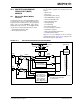
Figure 27-3 shows a typical connection between two
devices configured as master and slave.
FIGURE 27-3: I
2
C MASTER/SLAVE
CONNECTION
The I
2
C bus can operate with one or more master
devices and one or more slave devices.
There are four potential modes of operation for a given
device:
• Master Transmit mode
(master is transmitting data to a slave)
• Master Receive mode
(master is receiving data from a slave)
•Slave Transmit mode
(slave is transmitting data to a master)
• Slave Receive mode
(slave is receiving data from the master)
To begin communication, a master device starts out in
Master Transmit mode. The master device sends out a
Start bit followed by the address byte of the slave it
intends to communicate with. This is followed by a
single Read/Write bit, which determines whether the
master intends to transmit to or receive data from the
slave device.
If the requested slave exists on the bus, it will respond
with an Acknowledge bit, otherwise known as an ACK
.
The master then continues in either Transmit mode or
Receive mode and the slave continues in the
complement, either in Receive mode or Transmit
mode, respectively.
A Start bit is indicated by a high-to-low transition of the
SDA line while the SCL line is held high. Address and
data bytes are sent out, Most Significant bit (MSb) first.
The Read/Write bit is sent out as a logical one when the
master intends to read data from the slave, and is sent
out as a logical zero when it intends to write data to the
slave.
The Acknowledge bit (ACK
) is an active-low signal,
which holds the SDA line low to indicate to the
transmitter that the slave device has received the
transmitted data and is ready to receive more.
The transition of a data bit is always performed while
the SCL line is held low. Transitions that occur while the
SCL line is held high are used to indicate Start and Stop
bits.
If the master intends to write to the slave, then it
repeatedly sends out a byte of data, with the slave
responding after each byte with an ACK
bit. In this
example, the master device is in Master Transmit
mode, and the slave is in Slave Receive mode.
If the master intends to read from the slave, then it
repeatedly receives a byte of data from the slave, and
responds after each byte with an ACK
bit. In this
example, the master device is in Master Receive mode,
and the slave is Slave Transmit mode.
On the last byte of data communicated, the master
device may end the transmission by sending a Stop bit.
If the master device is in Receive mode, it sends the
Stop bit in place of the last ACK
bit. A Stop bit is
indicated by a low-to-high transition of the SDA line,
while the SCL line is held high.
In some cases, the master may want to maintain
control of the bus and re-initiate another transmission.
If so, the master device may send another Start bit in
place of the Stop bit or last ACK
bit when it is in receive
mode.
The I
2
C bus specifies three message protocols:
• Single message where a master writes data to a
slave
• Single message where a master reads data from
a slave
• Combined message where a master initiates a
minimum of two writes, or two reads, or a
combination of writes and reads, to one or more
slaves
When one device is transmitting a logical one, or letting
the line float, and a second device is transmitting a
logical zero, or holding the line low, the first device can
detect that the line is not a logical one. This detection,
when used on the SCL line, is called clock stretching.
Clock stretching gives slave devices a mechanism to
control the flow of data. When this detection is used on
the SDA line, it is called arbitration. Arbitration ensures
that there is only one master device communicating at
any single time.
Master
SCL
SDA
SCL
SDA
Slave
V
DD
V
DD