
Datasheet


2013 Microchip Technology Inc. DS22331A-page 145
MCP19111
27.0 MASTER SYNCHRONOUS
SERIAL PORT (MSSP)
MODULE
27.1 Master SSP (MSSP) Module
Overview
The Master Synchronous Serial Port (MSSP) module is
a serial interface useful for communicating with other
peripheral or microcontroller devices. These peripheral
devices may be Serial EEPROMs, shift registers,
display drivers, A/D converters, etc. The MSSP module
only operates in Inter-Integrated Circuit (I
2
C) mode.
• Serial Peripheral Interface (SPI)
• Inter-Integrated Circuit (I
2
C)
The I
2
C interface supports the following modes and
features:
•Master mode
• Slave mode
• Byte NACKing (Slave mode)
• Limited Multi-Master support
• 7-bit and 10-bit addressing
• Start and Stop interrupts
• Interrupt masking
• Clock stretching
• Bus collision detection
• General call address matching
• Dual Address masking
• Address Hold and Data Hold modes
• Selectable SDA hold times
Figure 27-1 is a block diagram of the I
2
C interface
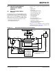
module in Master mode. Figure 27-2 is a diagram of the
I
2
C interface module in Slave mode.
FIGURE 27-1: MSSP BLOCK DIAGRAM (I
2
C MASTER MODE)
Read Write
SSPSR
Start bit, Stop bit,
Start bit detect,
SSPBUF
Internal
data bus
Set/Reset: S, P, SSPSTAT, WCOL, SSPxOV
Shift
Clock
MSb
LSb
SDA
Acknowledge
Generate (SSPCON2)
Stop bit detect
Write collision detect
Clock arbitration
State counter for
end of XMIT/RCV
SCL
SCL in
Bus Collision
SDA in
Receive Enable (RCEN)
Clock Cntl
Clock arbitrate/BCOL detect
(Hold off clock source)
[SSPM 3:0]
Baud rate
Reset SEN, PEN (SSPCON2)
generator
(SSPADD)
Address Match detect
Set SSPIF, BCLIF