Datasheet
Manuals
Brands
MICROCHIP TECHNOLOGY Manuals
Dev Kits
PCB design board
21
22
23
24
25
26
27
28
29
30
Table Of Contents
Preface
Introduction
Document Layout
Conventions Used in this Guide
Recommended Reading
The Microchip Web Site
Customer Support
Document Revision History
Chapter 1. Product Overview
1.1 Introduction
1.2 What is the MCP1631HV Digitally Controlled Programmable Current Source Reference Design?
1.3 What the MCP1631HV Digitally Controlled Programmable Current Source Kit Includes
Chapter 2. Installation and Operation
2.1 Introduction
2.2 Features
2.3 Getting Started
Appendix A. Schematic and Layouts
A.1 Introduction
A.2 Board – Schematic
A.3 Board – Top Solder Pads and Silk-Screen Layers
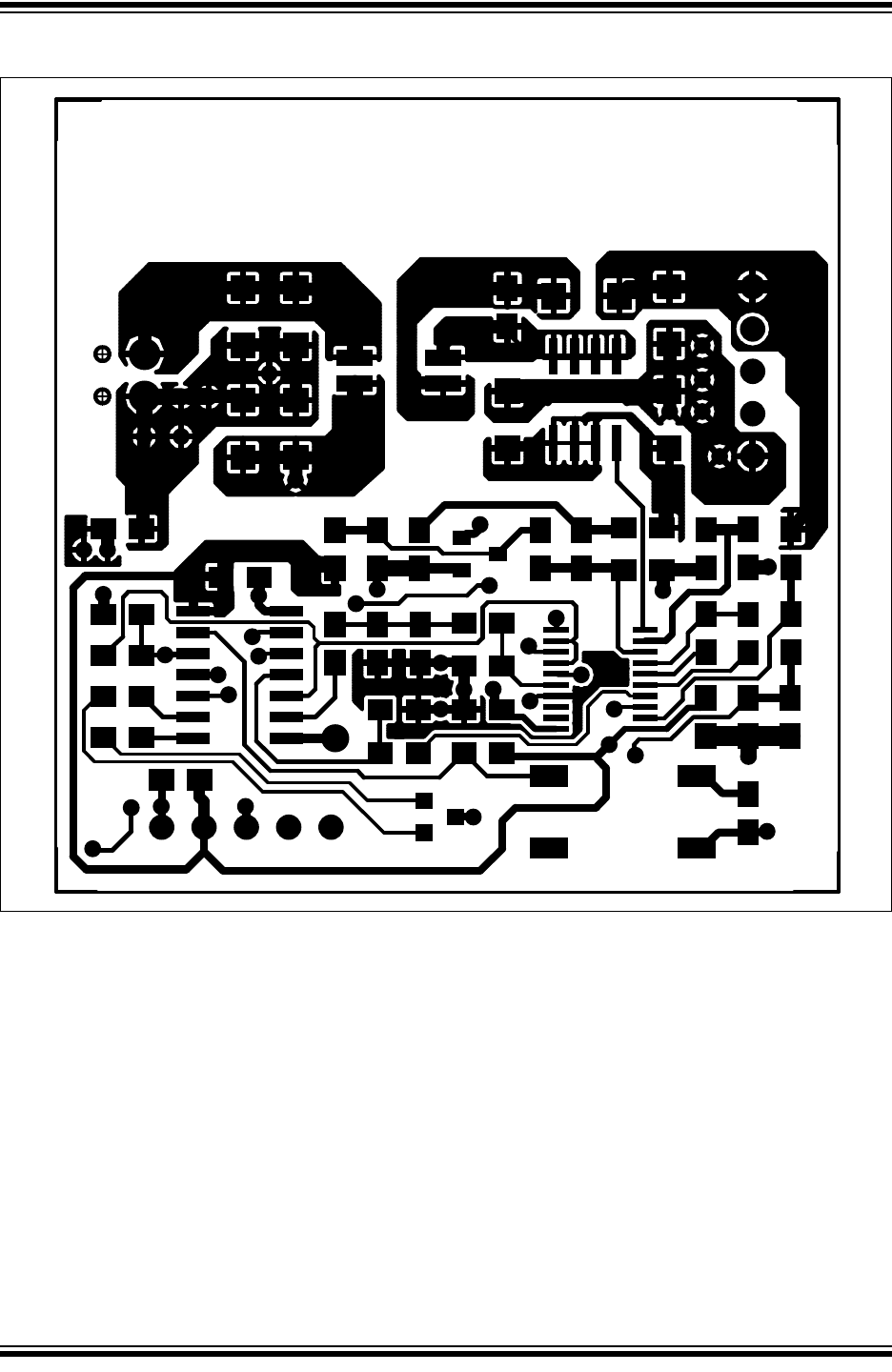
A.4 Board – Top Copper Layer
A.5 Board – Bottom Copper Layer
Appendix B. Bill Of Materials (BOM)
Appendix C. Demo Board Firmware
C.1 Summary Device Firmware Flowchart - LED Driver
C.2 Summary Device Firmware Flowchart - Li-Ion Charger
C.3 Summary Device Firmware Flowchart - NiMH/NiCd Charger
Worldwide Sales and Service
MCP1631HV Digitally Controlled Progra
mmable Current Source Reference Design
DS51798A-page 20
©
2009 Microchip Technology Inc.
A.4
BOARD – T
OP COPPE
R LAYER
1
...
...
22
23
24
25
26
...
...
32