
Datasheet


Table Of Contents
MCP1631HV Digitally Controlled Programmable Current Source Reference Design
DS51798A-page 12 © 2009 Microchip Technology Inc.
2.3.1.3 USING THE REFERENCE BOARD
The push button is used to switch the output ON or OFF (Standby). The first pressing
of the power button will turn on the board and drive the output at 10% of programmed
current (70 mA for the default firmware). The GREEN LED will flash with a 1 second
period, indicating that it is in normal operating mode.
The board is capable of a 10:1 dimming ratio. Each additional pressing of the power
button will increment the output drive current by 10% of the programmed drive current
up to the actual programmed drive current value.
To switch the output OFF, press and hold the push button for about 2 seconds until the
LED turns RED.
2.3.1.4 STATUS AND FAULT INDICATION
The MCP1631HV Digitally Programmable Current Source Reference Design has a
dual color (red/green) LED to indicate the status and faults. Table 2-1 shows the status
of the LEDs during various states of operating modes.
If a no load, overvoltage, or overtemperature fault condition occurs during operation,
the fault condition will be indicated by a flashing RED LED.
The RED LED will flash at a 1 Hz rate if an overtemperature condition has been
detected. An overtemperature condition will result in Thermal Shutdown.
The RED LED will flash at a 2 Hz rate if an overvoltage or missing load condition has
been detected. An overvoltage or missing load condition will result in an Overvoltage
Shutdown.
A fault condition must exist for 5 consecutive firmware sampling periods to be validated
as a hard fault.
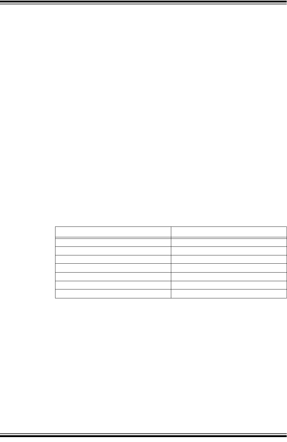
TABLE 2-1: STATUS OUTPUT
STATE / FAULT LED Status
Standby / Charge Complete State GREEN ON
ON (Dimming or Charging) State GREEN Flashing
Switching to Standby State RED ON after button press delay
Over Temperature Fault RED Flashing (1 Hertz)
Over Voltage Fault RED Flashing (2 Hertz)
Charge Timeout Fault RED Flashing (2 Hertz)
Calibration Complete State YELLOW (both LEDs ON)