
User`s guide


MCP1630 Dual Buck Demo Board User’s Guide
© 2005 Microchip Technology Inc. DS51531A-page 9
2.3.3 Programming
1. The MCP1630 Dual Buck Demo Board can be programmed to calibrate V
OUT1
,
V
OUT2
, output sequencing or tracking and switching frequency dithering on or off.
2. To enter the programming mode, apply input voltage within the specified
operating range (9V to 13.5V). Press and hold the M (SW1) button. While still
holding the M button, press and release the on/off (SW3) button. The flashing
rate of LED D1 should increase, indicating Programming mode.
3. Once in Programming mode, the first variable to set is V
OUT1
. Press the select S
button to increase V
OUT1
. Keep pressing the S button to increase V
OUT1
until it
wraps around to the minimum setting.
4. Press M once to select V
OUT2
. V
OUT2
in increased by pressing the S button
similar to setting V
OUT1
.
5. Press M once to select between output sequencing or tracking. D1 flashing
indicates that sequencing is selected. Press M to change from sequencing to
tracking, or from tracking to sequencing.
6. Press M once to select between frequency dithering on and frequency dithering
off. D1 flashing indicates that frequency dithering is selected.
7. By pressing and holding the M button, the selected settings will be programmed.
The next power-up cycle for the converter will return to the programmed settings.
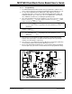
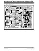
FIGURE 2-1: Mode, Select and On/Off Switch Location.
Note: The range of V
OUT1
is controlled by the value of fixed resistors R
34
, R
35
and
R
10
. The range of V
OUT1
is typically from 2.42V (minimum) to 3.39V
(maximum).
Note: The range of V
OUT2
is controlled by the value of fixed resistors R
14
, R
15
and
R
42
. The range of V
OUT2
is typically from 1.22V (minimum) to 2.3V
(maximum).
BOAR D
On/Off
Select
Mode