MCP1630 Dual Buck Demo Board User’s Guide © 2005 Microchip Technology Inc.
Note the following details of the code protection feature on Microchip devices: • Microchip products meet the specification contained in their particular Microchip Data Sheet. • Microchip believes that its family of products is one of the most secure families of its kind on the market today, when used in the intended manner and under normal conditions. • There are dishonest and possibly illegal methods used to breach the code protection feature.
MCP1630 DUAL BUCK DEMO BOARD USER’S GUIDE Table of Contents Preface ........................................................................................................................... 1 Chapter 1. Product Overview ........................................................................................ 5 1.1 1.2 1.3 Introduction ............................................................................................... 5 What is the MCP1630 Dual Buck Demo Board? .................................
MCP1630 Dual Buck Demo Board User’s Guide NOTES: DS51531A-page iv © 2005 Microchip Technology Inc.
MCP1630 DUAL BUCK DEMO BOARD USER’S GUIDE Preface NOTICE TO CUSTOMERS All documentation becomes dated, and this manual is no exception. Microchip tools and documentation are constantly evolving to meet customer needs, so some actual dialogs and/or tool descriptions may differ from those in this document. Please refer to our web site (www.microchip.com) to obtain the latest documentation available. Documents are identified with a “DS” number.
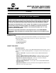
MCP1630 Dual Buck Demo Board User’s Guide Conventions Used in this Guide This manual uses the following documentation conventions: DOCUMENTATION CONVENTIONS Description Arial font: Italic characters Initial caps Quotes Underlined, italic text with right angle bracket Bold characters ‘bnnnn Text in angle brackets < > Courier font: Plain Courier Italic Courier 0xnnnn Square brackets [ ] Curly brackets and pipe character: { | } Ellipses...
Preface THE MICROCHIP WEB SITE Microchip provides online support via our web site at www.microchip.com. This web site is used as a means to make files and information easily available to customers.
MCP1630 Dual Buck Demo Board User’s Guide NOTES: DS51531A-page 4 © 2005 Microchip Technology Inc.
MCP1630 DUAL BUCK DEMO BOARD USER’S GUIDE Chapter 1. Product Overview 1.1 INTRODUCTION The MCP1630 Dual Buck Demo Board is used to evaluate the Microchip MCP1630 analog, high-speed Pulse Width Modulator (PWM) used in a dual synchronous, buck regulator, power-converter application. The evaluation board is a complete, stand-alone, dual-output, dc-dc converter with +12V input, adjustable dual output at 20A per output.
MCP1630 Dual Buck Demo Board User’s Guide 1.2 WHAT IS THE MCP1630 DUAL BUCK DEMO BOARD? The MCP1630 Dual Buck Demo Board is a complete, stand-alone, dual-output power supply capable of 20A per output, powered from a +12V input source. This board utilizes Microchip’s MCP1630 (high-speed PIC ® MCU PWM MSOP8), PIC16F684 (MCU Flash TSSOP14), MCP6231U (Op Amp SC-70) and TC6501 (Temperature Switch SOT23A-5). The input voltage range for the demo board is +9.0V to +13.5V.
MCP1630 DUAL BUCK DEMO BOARD USER’S GUIDE Chapter 2. Installation and Operation 2.1 INTRODUCTION The MCP1630 Dual Buck Demo Board demonstrates Microchip’s MCP1630 high-speed PWM, used in an adjustable, dual-output, buck regulator application. The MCP1630 is a high-speed, microcontroller-adaptable, PWM that, when used in conjunction with a microcontroller, will control the power system duty cycle to provide output voltage regulation.
MCP1630 Dual Buck Demo Board User’s Guide 2.3.1 Power Input and Output Connections Powering the MCP1630 Dual Buck Demo Board. 1. Apply the input voltage to the connector (J3) provided. Connect the positive side of the input source (+) to the test point (J3-1). Connect the negative (or return side (-)) of the input source to the GND terminal (J3-2). J3 is the center two position terminal block located on the left side of the board.
MCP1630 Dual Buck Demo Board User’s Guide 2.3.3 Programming 1. The MCP1630 Dual Buck Demo Board can be programmed to calibrate VOUT1, VOUT2, output sequencing or tracking and switching frequency dithering on or off. 2. To enter the programming mode, apply input voltage within the specified operating range (9V to 13.5V). Press and hold the M (SW1) button. While still holding the M button, press and release the on/off (SW3) button. The flashing rate of LED D1 should increase, indicating Programming mode. 3.
MCP1630 Dual Buck Demo Board User’s Guide NOTES: DS51531A-page 10 © 2005 Microchip Technology Inc.
MCP1630 DUAL BUCK DEMO BOARD USER’S GUIDE Appendix A. Schematic and Layouts A.1 INTRODUCTION AND HIGHLIGHTS This appendix contains the following schematics and layouts for the MCP1630 Dual Buck Demo Board: • • • • • • Board Schematic Board Outline Board - Top Layer Board - Mid Layer 1 Board - Mid Layer 2 Board - Bottom Layer © 2005 Microchip Technology Inc.
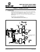
MCP1630 DUAL BUCK DEMO BOARD USER’S GUIDE BOARD SCHEMATIC - SHEET 1 S U3 G G S D D A.2 DS51531A-page 12 © 2005 Microchip Technology Inc.
BOARD SCHEMATIC - SHEET 2 © 2005 Microchip Technology Inc. S D G G S D A.
MCP1630 DUAL BUCK DEMO BOARD USER’S GUIDE A.4 BOARD OUTLINE 0.175 BOARD 0.175 DS51531A-page 14 © 2005 Microchip Technology Inc.
A.5 BOARD TOP LAYER BOARD © 2005 Microchip Technology Inc.
MCP1630 DUAL BUCK DEMO BOARD USER’S GUIDE A.6 BOARD MID-LAYER 1 BOARD DS51531A-page 16 © 2005 Microchip Technology Inc.
A.7 BOARD MID-LAYER 2 BOARD MIDLAYER2 © 2005 Microchip Technology Inc.
MCP1630 DUAL BUCK DEMO BOARD USER’S GUIDE A.8 BOARD BOTTOM LAYER DS51531A-page 18 © 2005 Microchip Technology Inc.
MCP1630 DUAL BUCK DEMO BOARD USER’S GUIDE Appendix B. Bill-Of-Materials (BOM) TABLE B-1: Qty 9 BILL-OF-MATERIALS Reference (BOM) Description ECJ-1VB1A105K CAP 1500PF 50V CERAMIC NPO 0603 CAP 220UF 4V AO X7343 CAP 9.0PF 50V CERAMIC NPO 0603 CAP .10UF 10V CERAMIC X7R 0603 Panasonic - ECG Kemet Electronics® Panasonic - ECG Kemet Electronics ECJ-1VB1H152K A700X227M004ATE015 ECJ-1VC1H090D C0603C104K8RACTU CAP 4.7UF 10V CERAMIC X5R 0603 CAP .
MCP1630 Dual Buck Demo Board User’s Guide TABLE B-1: BILL-OF-MATERIALS (BOM) (CONTINUED) Qty Reference 1 3 2 1 1 3 2 2 1 1 1 3 1 1 R14 R26, R40, R51 R28, R49 R30 R32 R33, R36, R48 R34, R41 R35, R42 R37 R38 R47 SW1, SW2, SW3 T1 TP6 RES 22.1K OHM 1/16W 1% 0603 SMD RES 3.01K OHM 1/16W 1% 0603 SMD RES 30.1K OHM 1/16W 1% 0603 SMD RES 4.75K OHM 1/16W 1% 0603 SMD RES 2.0K OHM 1/10W 5% 0603 SMD RES 100K OHM 1/16W 1% 0603 SMD RES 15.0K OHM 1/16W 1% 0603 SMD RES 10.0K OHM 1/16W 1% 0603 SMD RES 2.
MCP1630 DUAL BUCK DEMO BOARD USER’S GUIDE Appendix C. Evaluation Board Firmware C.1 DEVICE FIRMWARE For the latest version of the MCP1630 Dual Buck Demo Board firmware, visit the Microchip web site at www.microchip.com.
WORLDWIDE SALES AND SERVICE AMERICAS ASIA/PACIFIC ASIA/PACIFIC EUROPE Corporate Office 2355 West Chandler Blvd. Chandler, AZ 85224-6199 Tel: 480-792-7200 Fax: 480-792-7277 Technical Support: http://support.microchip.com Web Address: www.microchip.