
User`s guide


Installation and Operation
© 2007 Microchip Technology Inc. DS51665B-page 11
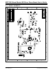
2.5.3 Dimming Control
An external potentiometer can optionally be attached to the PCB to provide LED
dimming control. When a potentiometer is present, the demonstration software will
sample the voltage and modulate pin GP5 (MCP1630 reference) with a low-frequency
PWM signal. The PWM signal is generated in software using Timer0 as a timing
reference. The software PWM signal provides 63 LED brightness levels. If a
potentiometer is not present, pin GP5 is maintained at 100% duty to provide full LED
brightness.
If potentiometer dimming is desired, connect a 10 kohm potentiometer to the ICSP
programming header, J3. The resistive element of the potentiometer is connected
between pins 2 and 3 of J3 (Vdd and ground). The potentiometer wiper is connected to
pin 5 of J3 (GP1 pin).
The demonstration software detects whether a potentiometer has been attached to the
PCB using the weak pull-up (WPU) feature on pin GP1. At startup, the software
enables pin GP1 as a digital input with the WPU turned on. If no potentiometer is
present, the pin will float high due to the WPU and a logical '1' will be detected. If a
potentiometer is connected and the wiper is turned to the minimum setting, a logical '0'
will be detected on the I/O pin. If the potentiometer is detected, the ADC result is
allowed to set the dimming duty cycle.
2.5.4 Modifications
The hardware and software on this demonstration board can be modified to solve a
wide variety of application problems. A few modifications that you might desire to
support your application are described below.
1. The reference voltage divider network comprising R4, R5, and R6 can be
modified to provide current output levels other than 350 mA and 700 mA. The
reference voltage supplied to the MCP1630 should be 560 mV or less to keep
the output current from exceeding 1A.
2. Some applications are sensitive to electromagnetic interference (EMI). One way
to reduce the impact of radiated EMI is to spread the noise across a portion of
the frequency spectrum. This is easy to do with the PIC12F683 by writing a value
to a tuning register that affects the frequency of the internal 8 MHz oscillator. If
you need this feature, uncomment the first four lines of code after the MainLoop
label in the code. This code reads a value from the free-running Timer0 and uses
it as a pseudo-random tuning value for the oscillator.
3. The switching frequency is set to 500 kHz to keep the size of inductor L1 small.
The clock frequency is set by the PR2 register, which is the timebase period reg-
ister for the PIC12F683 CCP module. Other switching frequencies can be used
by writing a different value to PR2. The CCPR1L and CCP1CON registers also
need to be modified to adjust the duty cycle of the clock signal. Refer to the
PIC12F683 data sheet (DS41211) for more information.
4. A temperature sensor can also be used for thermal management of the LEDs.
Microchip Technology, Inc. provides a range of analog and digital output
temperature sensors for different application needs. The ICSP programming
header (J3) on the PCB provides a convenient method to access 5V, ground, and
two I/O pins. These pins could be used to interface a temperature sensor to the
PIC12F683, if desired.
Note: Set the potentiometer to provide 0 output voltage when power is first
applied to the demo board. This will allow the potentiometer to be properly
detected as explained below.