
User`s guide


MCP1630 Boost Mode LED Driver Demo Board User’s Guide
DS51665B-page 8 © 2007 Microchip Technology Inc.
2.3 SETUP PROCEDURES
To operate the demonstration board, you need to complete the following steps:
1. Configure the board for the desired current output level.
2. Attach a LED load to the output terminals.
3. Connect a power supply to the input.
Detailed instructions are provided below for each step.
2.3.1 Demo Board Output Current Configuration
1. Remove jumper J4 for an output current of 350 mA. Install jumper J4 for an
output current of 700 mA.
2.3.2 Connecting the Load
A string of five LEDs mounted on a metal PCB has been provided for use with the demo
board. (See Figure 2-1).
When driven at 350 mA, the total power delivered to the five LEDs will be approximately
5 W. At 700 mA drive, the load power will be approximately 10W. Care must be taken
not to operate the LEDs beyond the maximum junction temperature specified in the
data sheet.
It is recommended that you mount the metal PCB to a heat-sink to allow continuous
operation. A heat-sink can be constructed using a length of 1-inch square aluminum
square tubing. The aluminum square tubing is available at most hardware stores. The
LED PCB can be mounted to the aluminum tubing using machine screws or self-tap-
ping sheet metal screws.
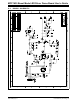
1. Connect the LED PCB to the demo board output terminals (TP1 and TP2) using
test clips (provided). The anode of the LEDs is indicated on the PCB with a '+'
marking and should be connected to the TP1 terminal on the demo board. The
cathode of the LEDs should be connected to the TP2 output terminal on the
demo board.
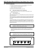
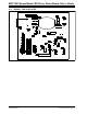
FIGURE 2-1: LED Load Board.
Note: Do not operate the LEDs for an extended period of time without mounting
the PCB to a suitable heat-sink. Operation beyond the maximum junction
temperature could cause early failure of the LEDs.
Note: Do not connect the TP2 output terminal on the demo board or the cathode
of the LEDs to circuit ground. The TP2 terminal is connected to a current
sensing resistor and is not at ground potential during normal operation.
Damage to the circuit will occur if the TP2 terminal is connected to ground.
+ + + ++
Connector wire
with 'alligator'
clip
D1 D2 D3 D4 D5
Connect to TP2Connect to TP1