
User`s guide

MCP1630 BOOST MODE LED DRIVER
DEMO BOARD USER’S GUIDE
© 2007 Microchip Technology Inc. DS51665B-page 7
Chapter 2. Installation and Operation
2.1 GETTING STARTED
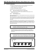
The MCP1630 Boost Mode LED Driver Demo Board is fully assembled and tested. The
board requires the use of an external input voltage source (+9V to 16V) and an external
LED load (provided).
2.2 WHAT THE MCP1630 BOOST MODE LED DRIVER DEMO BOARD KIT
INCLUDES
The MCP1630 Boost Mode LED Driver Demo Board Kit includes:
• MCP1630 Boost Mode LED Driver Demo Board (102-00152)
• A PCB containing a string of LEDs
• Analog and Interface Products Demonstration Boards CD-ROM (DS21912):
- MCP1630 Boost Mode LED Driver Demo Board User’s Guide (DS51665)
2.2.1 Additional Components Required for Operation
1. A DC Power Supply. A 2.5 mm plug with positive polarity on the center pin is
required to connect the power supply to J1. A bench supply that can produce
12V, 2.5A is recommended to operate the board at the full rated power. A 9V,
750 mA power supply can be purchased through Microchip Inc., part #
AC162039, if needed. This power supply will drive the supplied string of LEDs at
350 mA only (5W output).
2. Oscilloscope and/or multi-meter to observe waveforms and measure electrical
parameters (optional).