
User`s guide


MCP1630 Boost Mode LED Driver Demo Board User’s Guide
DS51665B-page 6 © 2007 Microchip Technology Inc.
1.3 DEVICE SUMMARY
The MCP1630 Boost Mode LED Driver Demo Board uses the following primary devices
on the board.
• A MCP1702 LDO regulator is used to supply the regulated voltage to the
PIC12F683 and the MCP1630. The MCP1702 is capable of delivering 250 mA
with only 650 mV (typical) of input to output voltage differential
• A MCP1630, a high-speed pulse width modulator IC, is used. When used in
conjunction with a microcontroller, the MCP1630 will control the power system
duty cycle to provide output current and/or voltage regulation
• A PIC12F683 microcontroller (MCU) is used to generate the MCP1630 reference
voltage and the oscillator signal at 500 kHz
1.4 TECHNICAL SPECIFICATIONS
• Input Voltage: +9V to 16V
• Maximum Output Voltage: 50V (limited to 40V by application software)
• Typical Output Current: 700 mA
• Maximum Output Current: 1A
• Maximum Output Power: 30W
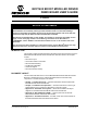
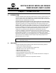
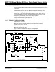
Figure 1-1 shows a simplified block diagram of the application
FIGURE 1-1: MCP1630 Boost Mode LED Driver Demo Board Simplified Block Diagram.
8
7
6
5
1
2
3
4
+
-
Output
Driver
+
-
Osc
Vref
EA
Comp
CS
8
7
6
5
1
2
3
4
VDD Vss
GP2/
CCP1
GP5
GP4
GP3
GP0
GP1
Vdd
Vss
+5
+5
+5
9 - 16 VDC
PIC12F683
MCP1630V
MCP1702
Clock
LED String
Bias Supply
Ramp Generator
Reference Circuit
Output Voltage Feedback