MCP1630 Boost Mode LED Driver Demo Board User’s Guide © 2007 Microchip Technology Inc.
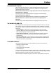
Note the following details of the code protection feature on Microchip devices: • Microchip products meet the specification contained in their particular Microchip Data Sheet. • Microchip believes that its family of products is one of the most secure families of its kind on the market today, when used in the intended manner and under normal conditions. • There are dishonest and possibly illegal methods used to breach the code protection feature.
MCP1630 BOOST MODE LED DRIVER DEMO BOARD USER’S GUIDE Table of Contents Preface ........................................................................................................................... 1 Introduction............................................................................................................ 1 Document Layout .................................................................................................. 1 Conventions Used in this Guide ...................................
MCP1630 Boost Mode LED Driver Demo Board User’s Guide NOTES: DS51665B-page iv © 2007 Microchip Technology Inc.
MCP1630 BOOST MODE LED DRIVER DEMO BOARD USER’S GUIDE Preface NOTICE TO CUSTOMERS All documentation becomes dated, and this manual is no exception. Microchip tools and documentation are constantly evolving to meet customer needs, so some actual dialogs and/or tool descriptions may differ from those in this document. Please refer to our web site (www.microchip.com) to obtain the latest documentation available. Documents are identified with a “DS” number.
MCP1630 Boost Mode LED Driver Demo Board User’s Guide CONVENTIONS USED IN THIS GUIDE This manual uses the following documentation conventions: DOCUMENTATION CONVENTIONS Description Arial font: Italic characters Represents Referenced books Emphasized text A window A dialog A menu selection A field name in a window or dialog A menu path MPLAB® IDE User’s Guide ...is the only compiler...
Preface RECOMMENDED READING This user's guide describes how to use MCP1630 Boost Mode LED Driver Demo Board. The following Microchip documents are available and recommended as supplemental reference resources. MCP1630/MCP1630V Data Sheet, "High-Speed, Microcontroller-Adaptable, Pulse Width Modulator" (DS21896) This data sheet provides detailed information regarding the MCP1630 family. PIC12F683 Data Sheet, (DS41211) This data sheet provides detailed information regarding the PIC12F683 product.
MCP1630 Boost Mode LED Driver Demo Board User’s Guide DOCUMENT REVISION HISTORY Revision B (June 2007) • • • • • Changed MCP1630 device to MCP1630V throughout document Added additional verbiage in Section 1.1 Introduction Updated Figure 1-1 Updated schematic to show MPC1630V device Changed MCP1630 device part number in BOM to MCP1630V device Revision A (May 2007) • Initial Release of this Document. DS51665B-page 4 © 2007 Microchip Technology Inc.
MCP1630 BOOST MODE LED DRIVER DEMO BOARD USER’S GUIDE Chapter 1. Product Overview 1.1 INTRODUCTION The MCP1630 Boost Mode LED Driver Demo Board is a step-up, switch-mode, dc-dc converter used for power LED applications. The demo board provides a 350 mA or 700 mA constant current source with a jumper selection. Other output currents can be obtained with minor modifications to the board. The MCP1630 Boost Mode LED Driver Demo Board utilizes Microchip's MCP1630V high-speed pulse width modulator.
MCP1630 Boost Mode LED Driver Demo Board User’s Guide 1.3 DEVICE SUMMARY The MCP1630 Boost Mode LED Driver Demo Board uses the following primary devices on the board. • A MCP1702 LDO regulator is used to supply the regulated voltage to the PIC12F683 and the MCP1630. The MCP1702 is capable of delivering 250 mA with only 650 mV (typical) of input to output voltage differential • A MCP1630, a high-speed pulse width modulator IC, is used.
MCP1630 BOOST MODE LED DRIVER DEMO BOARD USER’S GUIDE Chapter 2. Installation and Operation 2.1 GETTING STARTED The MCP1630 Boost Mode LED Driver Demo Board is fully assembled and tested. The board requires the use of an external input voltage source (+9V to 16V) and an external LED load (provided). 2.
MCP1630 Boost Mode LED Driver Demo Board User’s Guide 2.3 SETUP PROCEDURES To operate the demonstration board, you need to complete the following steps: 1. Configure the board for the desired current output level. 2. Attach a LED load to the output terminals. 3. Connect a power supply to the input. Detailed instructions are provided below for each step. 2.3.1 Demo Board Output Current Configuration 1. Remove jumper J4 for an output current of 350 mA. Install jumper J4 for an output current of 700 mA.
Installation and Operation 2.3.3 Powering the MCP1630 Boost Mode LED Driver Demo Board 1. Connect a power supply to J1 to power up the MCP1630 Boost Mode LED Driver Demo Board. Ensure that the power supply has a 2.5 mm barrel connector with the center pin positive. The input voltage source should be limited to the 9V to +16V range. Ensure that the chosen power supply can provide enough current at the selected voltage to properly power the LEDs.
MCP1630 Boost Mode LED Driver Demo Board User’s Guide The CCP output is also connected to a simple ramp generator that is reset at the beginning of each MCP1630 clock cycle. The ramp generator is composed of transistor Q2, resistors R2, R3 and capacitor C6. It provides the reference signal to the MCP1630 comparator. The MCP1630 comparator compares this ramp reference signal to the error amplifier output to generate a PWM signal.
Installation and Operation 2.5.3 Dimming Control An external potentiometer can optionally be attached to the PCB to provide LED dimming control. When a potentiometer is present, the demonstration software will sample the voltage and modulate pin GP5 (MCP1630 reference) with a low-frequency PWM signal. The PWM signal is generated in software using Timer0 as a timing reference. The software PWM signal provides 63 LED brightness levels.
MCP1630 Boost Mode LED Driver Demo Board User’s Guide 2.5.5 Programming Header J3 is provided for in-circuit programming. The MCP1630 Boost Mode LED Driver Demo Board comes pre-programmed with firmware to operate the system. The PIC12F683 can be reprogrammed with the PICkit 2 Debug Express (Microchip P/N: DV164121), which is a low-cost Flash microcontroller programmer and a debugger. DS51665B-page 12 © 2007 Microchip Technology Inc.
MCP1630 BOOST MODE LED DRIVER DEMO BOARD USER’S GUIDE Appendix A. Schematic and Layouts A.1 INTRODUCTION This appendix contains the following schematics and layouts for the MCP1630 Boost Mode LED Driver Demo Board: • • • • Board – Schematic Board – Top Layer Board – Top Silk Layer Board – Bottom Layer © 2007 Microchip Technology Inc.
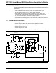
MCP1630 Boost Mode LED Driver Demo Board User’s Guide BOARD - SCHEMATIC 1 3 2 M A.2 DS51665B-page 14 © 2007 Microchip Technology Inc.
Schematic and Layouts A.3 BOARD - TOP LAYER © 2007 Microchip Technology Inc.
MCP1630 Boost Mode LED Driver Demo Board User’s Guide A.4 BOARD - TOP SILK LAYER DS51665B-page 16 © 2007 Microchip Technology Inc.
Schematic and Layouts A.5 BOARD - BOTTOM LAYER © 2007 Microchip Technology Inc.
MCP1630 Boost Mode LED Driver Demo Board User’s Guide NOTES: DS51665B-page 18 © 2007 Microchip Technology Inc.
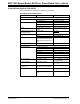
MCP1630 BOOST MODE LED DRIVER DEMO BOARD USER’S GUIDE Appendix B. Bill Of Materials (BOM) TABLE B-1: Qty BILL OF MATERIALS (BOM) Reference Description Manufacturer Rohm Part Number 1 C1 CAP TANT 4.7UF 16V 20% SMD 1206 5 C2, C3, C5, C10, C11 CAP CERM .
Bill Of Materials (BOM) TABLE B-1: Qty BILL OF MATERIALS (BOM) (CONTINUED) Reference Description Manufacturer Part Number 3 R9, R10, R15 DO NOT POPULATE — — 1 R11 RES 0.0 OHM 1/8W 5% 0805 SMD Rohm MCR10EZPJ000 1 R12 RES 8.2K OHM 1/8W 5% 0805 SMD Rohm MCR10EZPJ822 1 R13 RES 1.0K OHM 1/8W 5% 0805 SMD Rohm MCR10EZPJ102 1 R14 RESISTOR .
MCP1630 BOOST MODE LED DRIVER DEMO BOARD USER’S GUIDE Appendix C. Firmware Flowchart Start Initialize: GP2 (for Output PWM) And GP5 (for Output VREF Internal Osc Clock to 8 MHz, TMR0 = 0 Configure Ansel & CMCON0 as Digital I/O Set Weak Pull-Up on GP1 Setup CCP module and 20% duty cycle (Clock for MCP1630) Output VREF Signal through GP5 (Reference Voltage for MCP1630 ) Is GP1 = 1? YES NO 1. Clear Weak Pull-Up on GP1 2. Set a Flag for Potentiometer Detected 3.
MCP1630 Boost Mode LED Driver Demo Board User’s Guide A Set ADC for CH1 Is Overvoltage Flag set already? YES NO Check ADC for Overvoltage Is Delay expired? NO YES B NO Overvoltage? 1. Restart clock to MCP1630 2. Restart reference voltage to MCP1630 YES 1. Stop clock to MCP1630 2. Stop reference voltage to MCP1630 3. Initialize Delay for 25 mSec FIGURE C-2: DS51665B-page 22 Firmware Flowchart - Page 2. © 2007 Microchip Technology Inc.
Firmware Flowchart NOTES: © 2007 Microchip Technology Inc.
WORLDWIDE SALES AND SERVICE AMERICAS ASIA/PACIFIC ASIA/PACIFIC EUROPE Corporate Office 2355 West Chandler Blvd. Chandler, AZ 85224-6199 Tel: 480-792-7200 Fax: 480-792-7277 Technical Support: http://support.microchip.com Web Address: www.microchip.
Mouser Electronics Authorized Distributor Click to View Pricing, Inventory, Delivery & Lifecycle Information: Microchip: MCP1630DM-LED2