
Datasheet


Table Of Contents
- 2.0 MHz, 500 mA Synchronous Buck Regulator
- Package Types
- Typical Application Circuit
- Functional Block Diagram
- 1.0 Electrical Characteristics
- 2.0 Typical Performance Curves
- 3.0 Pin Descriptions
- 4.0 Detailed Description
- 5.0 Application Information
- 6.0 Typical Application Circuits
- 7.0 Packaging Information
- Appendix A: Revision History
- Product Identification System
- Trademarks
- Worldwide Sales and Service
2007-2012 Microchip Technology Inc. DS22042B-page 7
MCP1603/B/L
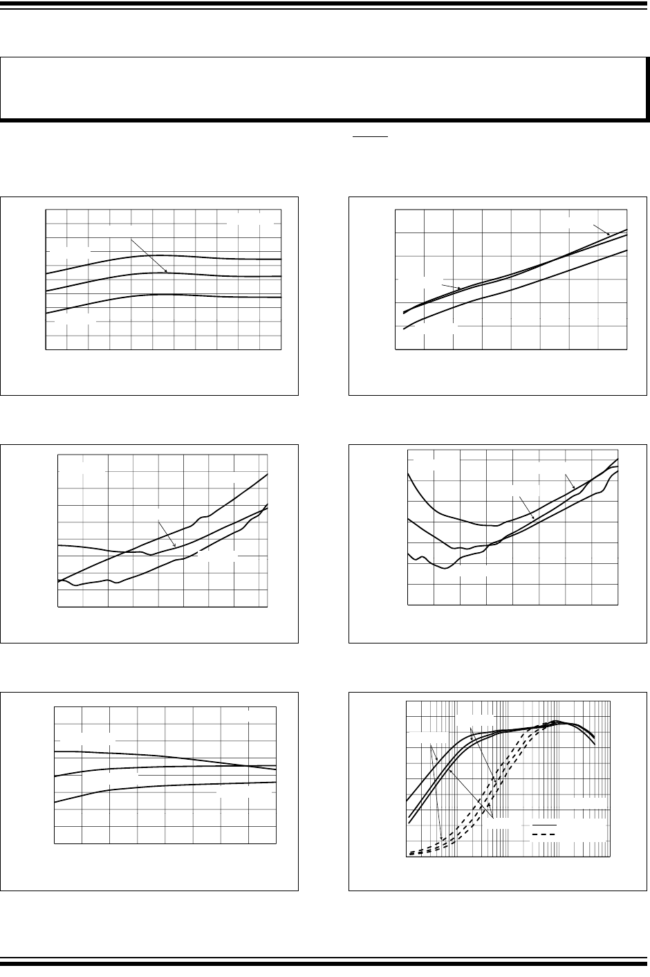
2.0 TYPICAL PERFORMANCE CURVES
Note: Unless otherwise indicated, MCP1603/L, V
IN
= SHDN =3.6V, C
OUT
=C
IN
= 4.7 µF, L = 4.7 µH,
V
OUT
(ADJ) = 1.8V, I
LOAD
= 100 mA, T
A
= +25°C. Adjustable or fixed output voltage options can be used to generate the
Typical Performance Characteristics.
FIGURE 2-1: PFM I
Q
vs. Ambient
Temperature (MCP1603/L).
FIGURE 2-2: PWM I
Q
vs. Ambient
Temperature (MCP1603B).
FIGURE 2-3: Efficiency vs. Input Voltage
(V
OUT
= 1.2V).
FIGURE 2-4: PFM I
Q
vs. Input Voltage
(MCP1603/L).
FIGURE 2-5: PWM I
Q
vs. Input Voltage
(MCP1603B).
FIGURE 2-6: Efficiency vs. Output Load
(V
OUT
= 1.2V).
Note: The graphs and tables provided following this note are a statistical summary based on a limited number of
samples and are provided for informational purposes only. The performance characteristics listed herein
are not tested or guaranteed. In some graphs or tables, the data presented may be outside the specified
operating range (e.g., outside specified power supply range) and therefore outside the warranted range.
42
43
44
45
46
47
48
49
50
e
scent Current (µA)
V
OUT
= 1.8V
V
IN
= 4.2V
V
=30V
V
IN
= 3.6V
40
41
42
-40 -25 -10 5 20 35 50 65 80 95 110 125
Qui
e
Ambient Temperature (
o
C)
V
IN
=3
.
0V
2.7
2.8
2.9
3
3.1
3.2
3.3
s
cent Current (mA)
V
OUT
= 1.8V
V
IN
= 3.0V
V
IN
=
3.6V
V
IN
= 4.2V
2.4
2.5
2.6
2.7
-40-25-10 5 2035506580
Quie
s
Ambient Temperature (
o
C)
V
IN
3.6V
70
75
80
85
90
95
100
Efficiency (%)
V
OUT
= 1.2V
I
OUT
= 100 mA
I
OUT
= 500 mA
I
OUT
= 300 mA
60
65
2.7 3.05 3.4 3.75 4.1 4.45 4.8 5.15 5.5
Input Voltage (V)
44
46
48
50
52
i
escent Current (µA)
T
A
= +25
o
C
T
A
= +90
o
C
40
42
2.7 3.05 3.4 3.75 4.1 4.45 4.8 5.15 5.5
Qu
i
Input Voltage (V)
T
A
= -40
o
C
2.6
2.8
3
3.2
3.4
s
cent Current (mA)
T
A
= +25
o
C
T
A
= +90
o
C
V
OUT
= 1.8V
2
2.2
2.4
2.7 3.05 3.4 3.75 4.1 4.45 4.8 5.15 5.5
Quie
s
Input Voltage (V)
T
A
= -40
o
C
30
40
50
60
70
80
90
100
E
fficiency (%)
V
OUT
= 1.2
V
V
IN
= 2.7V
V
IN
= 3.6V
0
10
20
30
0.1 1 10 100 1000
E
Output Current (mA)
OUT
V
IN
= 4.2V
PFM/PWM
PWM Only