
Datasheet


Table Of Contents
- 2.0 MHz, 500 mA Synchronous Buck Regulator
- Package Types
- Typical Application Circuit
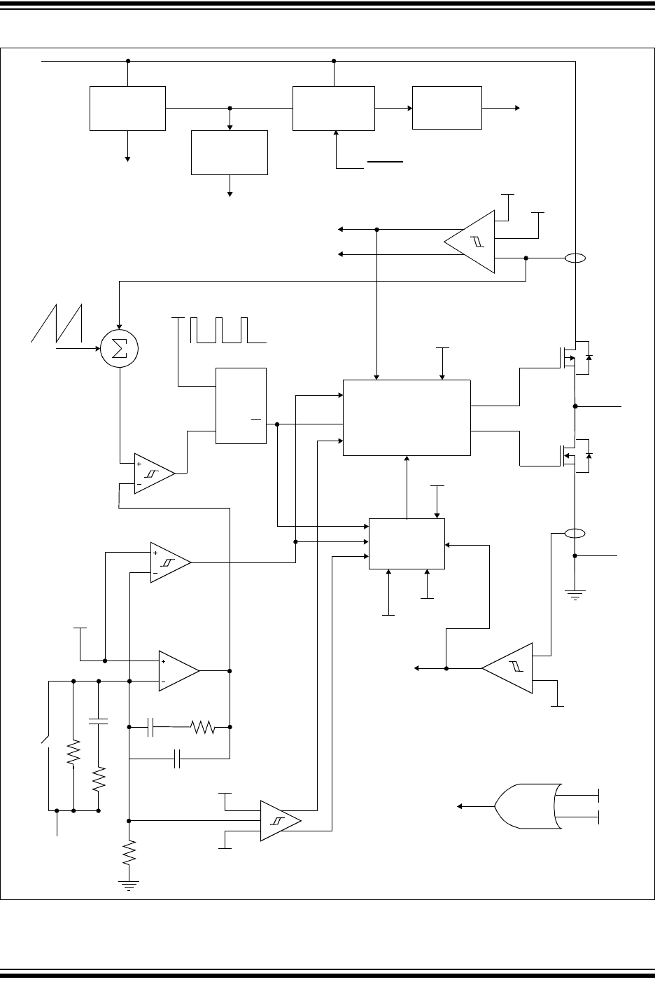
- Functional Block Diagram
- 1.0 Electrical Characteristics
- 2.0 Typical Performance Curves
- 3.0 Pin Descriptions
- 4.0 Detailed Description
- 5.0 Application Information
- 6.0 Typical Application Circuits
- 7.0 Packaging Information
- Appendix A: Revision History
- Product Identification System
- Trademarks
- Worldwide Sales and Service
2007-2012 Microchip Technology Inc. DS22042B-page 3
MCP1603/B/L
Functional Block Diagram
ILIM
PWM
ILIM
PFM
IPEAK
PWM
IPEAK
PFM
V
IN
SHDN
V
FB
/V
OUT
GND
L
X
Band
Gap
UVLO
Switch Drive
UVLO
V
REF
Logic and Timing
S
RQ
Q
Soft Start
V
REF
PWM/PFM
Logic
V
REF
Slope
Comp.
OSC
-I
PK
Limit
UVLO
Thermal
Shutdown
TSD
EA
POFF NOFF
PWM/PFM - PWM ONLY
TSD
PFM Error Amp
PWM Error Amp
OV Threshold
UV Threshold
I
PK
Limit
-ILPK
IPEAK
PWM
IPEAK
PFM
Disable
Switcher
-ILPK
PWM-ONLY
+
+