
Datasheet


Table Of Contents
- 2.0 MHz, 500 mA Synchronous Buck Regulator
- Package Types
- Typical Application Circuit
- Functional Block Diagram
- 1.0 Electrical Characteristics
- 2.0 Typical Performance Curves
- 3.0 Pin Descriptions
- 4.0 Detailed Description
- 5.0 Application Information
- 6.0 Typical Application Circuits
- 7.0 Packaging Information
- Appendix A: Revision History
- Product Identification System
- Trademarks
- Worldwide Sales and Service
MCP1603/B/L
DS22042B-page 18 2007-2012 Microchip Technology Inc.
5.6 Inductor Selection
When using the MCP1603, the inductance value can
range from 3.3 µH to 10 µH. An inductance value of
4.7 µH is recommended to achieve a good balance
between converter load transient response and
minimized noise.
The value of inductance is selected to achieve a
desired amount of ripple current. It is reasonable to
assume a ripple current that is 20% of the maximum
load current. The larger the amount of ripple current
allowed, the larger the output capacitor value becomes
to meet ripple voltage specifications. The inductor
ripple current can be calculated according to the
following equation.
EQUATION 5-4:
When considering inductor ratings, the maximum DC
current rating of the inductor should be at least equal to
the maximum load current, plus one half the peak-to-
peak inductor ripple current (1/2 x I
L
). The inductor
DC resistance adds to the total converter power loss.
An inductor with a low DC resistance allows for higher
converter efficiency.
5.7 Thermal Calculations
The MCP1603 is available in two different packages
(TSOT-23 and 2x3 DFN). The junction temperature is
estimated by calculating the power dissipation and
applying the package thermal resistance (
JA
). The
maximum continuous junction temperature rating for
the MCP1603 is +125°C.
To quickly estimate the internal power dissipation for
the switching buck regulator, an empirical calculation
using measured efficiency can be used. Given the
measured efficiency, the internal power dissipation is
estimated by the following equation:
EQUATION 5-5:
The difference between the first term, input power
dissipation, and the second term, power delivered, is
the internal power dissipation. This is an estimate
assuming that most of the power lost is internal to the
MCP1603. There is some percentage of power lost in
the buck inductor, with very little loss in the input and
output capacitors.
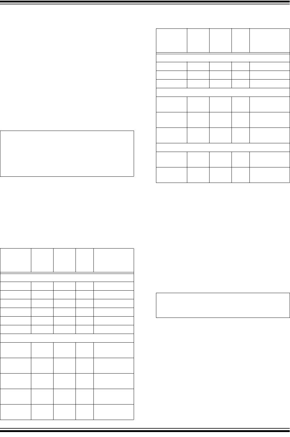
TABLE 5-2: MCP1603 RECOMMENDED
INDUCTORS
Part
Number
Value
(µH)
DCR
(max)
I
SAT
(A)
Size
WxLxH (mm)
Coiltronics
®
SD3110 3.3 0.195 0.81 3.1x3.1x1.0
SD3110 4.7 0.285 0.68 3.1x3.1x1.0
SD3110 6.8 0.346 0.58 3.1x3.1x1.0
SD3812 3.3 0.159 1.40 3.8x3.8x1.2
SD3812 4.7 0.256 1.13 3.8x3.8x1.2
SD3812 6.8 0.299 0.95 3.8x3.8x1.2
Würth Elektronik
®
WE-TPC
Type XS
3.3 0.225 0.72 3.3x3.5x0.95
WE-TPC
Type XS
4.7 0.290 0.50 3.3x3.5x0.95
WE-TPC
Type S
4.7 0.105 0.90 3.8x3.8x1.65
WE-TPC
Type S
6.8 0.156 0.75 3.8x3.8x1.65
WE-TPC
Type Tiny
4.7 0.100 1.7 2.8x2.8x2.8
I
L
V
OUT
F
SW
L
------------------- 1
V
OUT
V
IN
-------------–
=
Where:
F
SW
= Switching Frequency
Sumida
®
CMD4D06 3.3 0.174 0.77 3.5x4.3x0.8
CMD4D06 4.7 0.216 0.75 3.5x4.3x0.8
CMD4D06 6.8 0.296 0.62 3.5x4.3x0.8
Coilcraft
®
XFL3012-
332ME_
3.3 0.106 1.2 3x3x1.2
XFL3012-
472ME_
4.7 0.143 1.0 3x3x1.2
LPS4018-
103ML_
10 0.200 1.2 4x4x1.8
TDK-EPC
®
B82462_
G4472M
4.7 0.04 1.8 6x6x3
VLS3015E
T-4R7M
4.7 0.113 1.1 3x3x1.5
TABLE 5-2: MCP1603 RECOMMENDED
INDUCTORS (CONTINUED)
Part
Number
Value
(µH)
DCR
(max)
I
SAT
(A)
Size
WxLxH (mm)
V
OUT
I
OUT
Efficiency
-------------------------------------
V
OUT
I
OUT
– P
Diss
=