
User manual


!
www.rovingnetworks.com Version 1.1 9/20/2012 6
RN-131/171-PICTAIL-UM
3. Type the following commands in the console of your terminal emulator:
$$$ This command places the RN-131/RN-171 module in command mode.
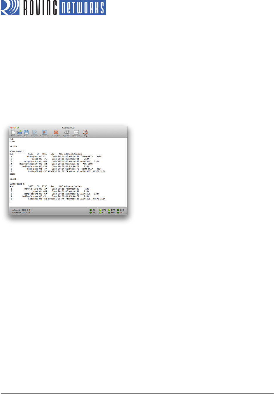
scan <cr> The device scans for networks and produces a list of available access points (see
Figure 3 for an example). The access point to which you wish to connect should be
listed. If it is not, repeat the scan command.
join # XX <cr> Associate with the access point, where XX is the access point’s number interest as
shown in the scan report.
leave <cr> This command asks the device to leave the network.
Figure 3. Access Point List
!
4. Store the parameters from step 3 into the RN-131/RN-171 module’s non-volatile memory so that they can be
used in the next application you run on the PIC18F87J11. Type the following commands in the console of your
terminal emulator:
set wlan ssid <string> <cr> Set the network’s SSID where <string> is the SSID (e.g., set wlan ssid
RovingNET).
set wlan pass <string> <cr> Set the passphrase to use when joining where <string> is the passphrase
(e.g., set wlan pass duckmauifries).
save <cr> Save the settings to persistent storage; reused when joining.
reboot <cr> Reboot the module so that the settings take effect.
Data Mode Operation
In the following steps you load an application into the PIC18F87J11 that allows the RN-131/RN-171 module to operate in
data mode and accept a telnet connection request. Additionally, the application lets you control the module’s LEDs by
sending specific PIC commands.
1. Configure the jumpers J4 and J13 as shown in Figure 4. This setting allows the PIC’s UART to communicate with
RN-131/RN-171 module’s UART via the PICtail connector, and also allows the module’s transmitted data to echo
back to the terminal emulator’s console. (This setting is specific to the PIC18 Explorer Board.)